

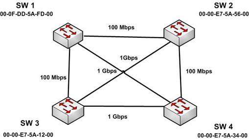
The four switches in the diagram below have default configurations. Considering the bandwidths indicated on
each link and the MAC addresses indicated for each switch, which ports will be forwarding after RSTP has
converged? (Choose all that apply.)

A.
SW 1 port that connects to SW 4
B.
SW 1 port that connects to SW 2
C.
SW 1 port that connects to SW 3
D.
SW 2 port that connects to SW 3
E.
SW 2 port that connects to SW 4
F.
SW 3 port that connects to SW 4
G.
SW 3 port that connects to SW 1
H.
SW 3 port that connects to SW 2
Explanation:
The ports that will be forwarding after convergence are the SW1 port that connects to SW4, the SW2 port that
connects to SW3, and all of the ports on SW3. The process of determining these port states occurs in this
order:
1. Selection of the root bridge. All ports on the root bridge become designated ports and are set to forward.
2. Determination of the root ports on each non-root bridge.
3. Determination of the designated port on each segment that does not connect directly to the root bridge.
4. Designated and root ports will be set to forwarding, and all other ports will be set to discarding.
For step 1, when all bridge priorities have been left to their default, all switches will have same bridge priority.
When that is the case, as in this scenario, the switch with the lowest MAC address will be selected as root
bridge. In this case, SW3 has the lowest MAC address and becomes the root bridge. ALL ports are in a
forwarding state on the root bridge, which explains why all of the ports on SW3 will be in a forwarding state.
For step 2, each non-root bridge will select the interface it possesses with the least cost path to the root bridge.
Once selected, that port will be placed in a forwarding state. 100 Mbps links will be assigned a cost of 19, and 1
Gbps links will be assigned a cost of 4. Each path cost is the cumulative cost of the links in the path. The root
ports for the non-root bridges are determined as follows.
SW1 has four paths to the root bridge, with each path yielding the following costs:
SW1 to SW3 (100 Mbps) cost = 19
SW1 to SW4 to SW3 (1 Gbps + 1 Gbps) cost = 4 + 4 = 8
SW1 to SW2 to SW 4 to SW3 (100 Mbps + 100 Mbps + 1 Gbps) cost = 19 + 19 + 4 = 42
SW1 to SW2 to SW3 (100 Mbps + 1 Gbps) cost = 19 + 4 = 23
SW1 will use the lowest cost path (SW1 to SW4 to SW3) as its root path. It will set the SW1 connection to SW4
to forwarding and the connection from SW1 to SW3 to blocking. The status of its third interface (SW1 to SW2)
will be determined in Step 3, since it is a shared segment with SW2 that does not have a direct connection to
the root bridge.
Switch 2 (SW2) has three paths to the root bridge, with each path yielding the following costs:
SW2 to SW3 (1 Gbps) cost = 4
SW2 to SW1 to SW3 (100 Mbps + 100 Mbps) cost = 19 + 19 = 38
SW2 to SW4 to SW3 (100 Mbps + 1 Gbps) cost = 19 + 4 = 23
SW2 will use the lowest cost path (SW2 to SW3) as its root path and will set the SW2 connection to SW3 to
forwarding. The status of its second and third interfaces (SW2 to SW1 and SW2 to SW4) will be determined in
step 3 since both are shared segments with SW2 and SW4 respectively that do not have a direct connection to
the root bridge.
Switch 4 (SW4) has four paths to the root bridge, with each path yielding the following costs:
SW4 to SW3 (1 Gbps) cost = 4
SW4 to SW1 to SW3 (1 Gbps + 100 Mbps) cost = 4+19 = 23
SW4 to SW2 to SW1 to SW3 (100 Mbps + 100 Mbps + 100 Mbps) cost = 19 + 19 + 19 = 57
SW4 to SW2 to SW3 (1 Gbps + 100 Mbps) cost = 4 +19 = 23
SW4 will use the lowest cost path (SW4 to SW3) as its root path and set the SW4 connection to SW3 to
forwarding. The status of SW4’s second and third interfaces, SW4 to SW1 and SW4 to SW2, will be
determined in step 3. Since these interfaces are shared segments with SW1 and SW2, they do not have a
direct connection to the root bridge.
For Step 3, there are two segments in the diagram (SW1 to SW2 and SW2 to SW4) that do not connect directly
to the root bridge. The interface on either end of the segment that has the least cost path to the root bridge will
be the designated port for that section.
The designated port of each segment is determined in this way.For the SW1 to SW2 segment, the SW2 end of the segment has a shortest path cost of 1 Gbps (4) to the
root, and the SW1 end of the segment has a shortest path cost through SW4 of 2 Gbps (8) to the root. The
SW2 port to SW1 will be the designated port and will be forwarding.
For the SW2 to SW4 segment, the SW2 end of the segment has a shortest path cost of 1 Gbps (4) to the
root and the SW4 end of the segment has a shortest path cost of 1 Gbps (4) to the root. This is a tie. In the
case of a tie, the interface connected to the switch with the lowest MAC address becomes the designated
port for the segment. SW4 has the lowest MAC address, so the SW4 port to SW2 will be the designated
port and will be forwarding.
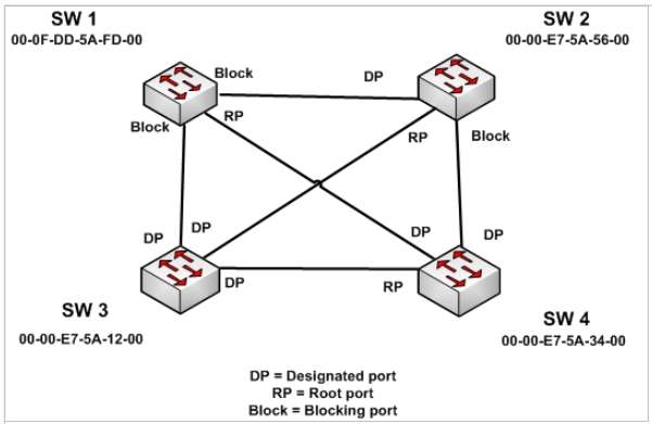
Once determined, the designated and root ports will be set to forwarding and all other ports will be set to
discarding. The converged state of all ports is shown in the diagram below.
Once STP has converged, the port states will determine the path used when sending traffic from a host
connected to one switch to a host connected to another switch. For example, if a host connected to SW3 were
destined for a host connected to SW2, the path taken would be SW3 to SW2. It would not take SW3-SW1-
SW2 or SW3-SW4-SW2 because on both of those paths, STP is blocking at least one port in the path.
Objective:
LAN Switching Fundamentals
Sub-Objective:
Configure, verify, and troubleshoot STP protocolsHome > Support > Technology Support > LAN Switching > Spanning Tree Protocol > Technology
Information>Technology White Paper>Understanding Rapid Spanning Tree Protocol (802.1w)
