

— Exhibit –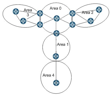
— Exhibit —
Click the Exhibit button.
You are asked to configure an OSPF virtual link that connects remote Area 4 to the backbone.
Referring to the exhibit, what are two requirements for an OSPF virtual link to operate correctly?
(Choose two.)

A.
A virtual link configuration on the ABR between Areas 0 and 1 must include transit area 1.
B.
The interface of the transit area must be of type vt.
C.
A virtual link configuration on the ABR between Areas 0 and 1 must be the interface address of
the neighbor on the far end.
D.
A virtual link configuration on the ABR between Areas 0 and 1 must be the router ID (RID) of
the neighbor on the far end.
Correct Answer
http://www.juniper.net/documentation/en_US/junos13.1/topics/example/ospf-virtual-links-configuring.html
Overview
If any routing device on the backbone is not physically connected to the backbone, you must establish a virtual connection between that routing device and the backbone to connect the noncontiguous areas.
To configure an OSPF virtual link through an area, you specify the router ID (IP address) of the routing devices at each end of the virtual link. These routing devices must be area border routers (ABRs), with one that is physically connected to the backbone. You cannot configure virtual links through stub areas. You must also specify the number of the area through which the virtual link transits (also known as the transit area). You apply these settings to the backbone area (defined by the area 0.0.0.0) configuration on the ABRs that are part of the virtual link.
In this example, Device R1 and Device R2 are the routing devices at each end of the virtual link, with Device R1 physically connected to the backbone, as shown in Figure 1. You configure the following virtual link settings:
neighbor-id—Specifies the IP address of the routing device at the other end of the virtual link. In this example, Device R1 has a router ID of 192.168.0.5, and Device R2 has a router ID of 192.168.0.3.
transit-area—Specifies the area identifier through which the virtual link transits. In this example, area 0.0.0.3 is not connected to the backbone, so you configure a virtual link session between area 0.0.0.3 and the backbone area through area 0.0.0.2. Area 0.0.0.2 is the transit area.
0
0