

In 802.1s, how is the VLAN to instance mapping represented in the BPDU?

A.
The VLAN to instance mapping is a normal 16-byte field in the MST BPDU.
B.
The VLAN to instance mapping is a normal 12-byte field in the MST BPDU.
C.
The VLAN to instance mapping is a 16-byte MD5 signature field in the MST BPDU.
D.
The VLAN to instance mapping is a 12-byte MD5 signature field in the MST BPDU.
Explanation:
MST Configuration and MST Region
Each switch running MST in the network has a single MST configuration that consists of these
three attributes:
1. An alphanumeric configuration name (32 bytes)
2. A configuration revision number (two bytes)
3. A 4096-element table that associates each of the potential 4096 VLANs supported on the
chassis to a given instance.
In order to be part of a common MST region, a group of switches must share the same
configuration attributes.
It is up to the network administrator to properly propagate the configuration throughout the region.
Currently, this step is only possible by the means of the command line interface (CLI) or through
Simple Network
Management Protocol (SNMP). Other methods can be envisioned, as the IEEE specification does
not explicitly mention how to accomplish that step.
Note: If for any reason two switches differ on one or more configuration attribute, the switches are
part of different regions. For more information refer to the Region Boundary section of this
document.
Region Boundary
In order to ensure consistent VLAN-to-instance mapping, it is necessary for the protocol to be able
to exactly identify the boundaries of the regions. For that purpose, the characteristics of the regionare included in the BPDUs. The exact VLANs-to-instance mapping is not propagated in the BPDU,
because the switches only need to know whether they are in the same region as a neighbor.
Therefore, only a digest of the VLANs-toinstance mapping table is sent, along with the revision
number and the name. Once a switch receives a BPDU, the switch extracts the digest (a
numerical value derived from the VLAN-to-instance mapping table through a mathematical
function) and compares this digest with its own computed digest. If the digests differ, the port on
which the BPDU was received is at the boundary of a region.
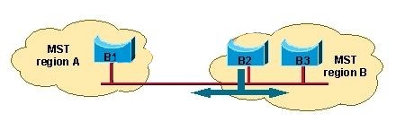
In generic terms, a port is at the boundary of a region if the designated bridge on its segment is in
a different region or if it receives legacy 802.1d BPDUs. In this diagram, the port on B1 is at the
boundary of region A, whereas the ports on B2 and B3 are internal to region B:
MST Instances
According to the IEEE 802.1s specification, an MST bridge must be able to handle at least these
two instances:
One Internal Spanning Tree (IST)
One or more Multiple Spanning Tree Instance(s) (MSTIs)
The terminology continues to evolve, as 802.1s is actually in a pre-standard phase. It is likely
these names will change in the final release of 802.1s. The Cisco implementation supports 16
instances: one IST (instance 0) and 15 MSTIs.
show vtp status
Cisco switches “show vtp status” Field Descriptions has a MD5 digest field that is a 16-byte
checksum of the
VTP configuration as shown below
Router# show vtp status
VTP Version: 3 (capable)
Configuration Revision: 1
Maximum VLANs supported locally: 1005
Number of existing VLANs: 37
VTP Operating Mode: Server
VTP Domain Name: [smartports]
VTP Pruning Mode: DisabledVTP V2 Mode: Enabled
VTP Traps Generation: Disabled
MD5 digest : 0x26 0xEE 0x0D 0x84 0x73 0x0E 0x1B 0x69
Configuration last modified by 172.20.52.19 at 7-25-08 14:33:43
Local updater ID is 172.20.52.19 on interface Gi5/2 (first layer3 interface fou)
VTP version running: 2http://www.cisco.com/en/US/tech/tk389/tk621/technologies_white_paper09186a0080094cfc.shtml
http://www.cisco.com/en/US/docs/ios-xml/ios/lanswitch/command/lsw-cr-book.pdf
