

what the effect is of this configuration sequence?
Refer to the configuration statements shown in the graphic above.
R1(config)#access-list 199 permit tcp host 10.1.1.1 host 172.16.1.1
R1(config)#access-list 199 permit tcp host 172.16.1.1 host 10.1.1.1
R1(config)#end
R1#debug ip packet 199 detail
Which statement reflects what the effect is of this configuration sequence?
What is the result if you configure two devices with the ntp server command?
What is the result if you configure two devices with the ntp server command?
which OSI layer is the problem most likely occurring?
A technician is troubleshooting connectivity problems between two routers that are directly
connected through a serial line. The technician notices that the serial line is up, but cannot see
any neighbors displayed in the output of the show cdp neighbors command.
In which OSI layer is the problem most likely occurring?
What are two approaches to maintaining a network?
What are two approaches to maintaining a network?(Choose two.)
FCAPS stands for:
DRAG DROP
FCAPS is a network maintenance model defined by ISO. FCAPS stands for: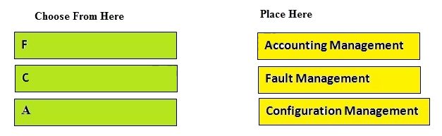
Match the model names on the left to the options on the right:
DRAG DROP
There are many Network Maintenance models. Match the model names on the left to the options on the right: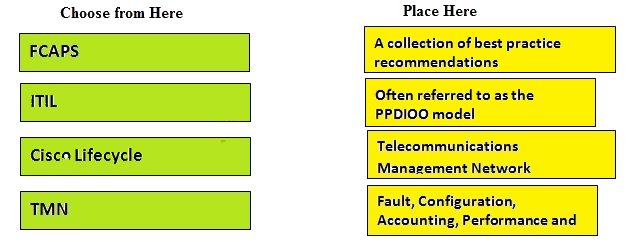
Match the items on the left to their purpose on the right.
DRAG DROP
Match the items on the left to their purpose on the right.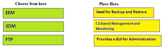
which device is the fault condition located?
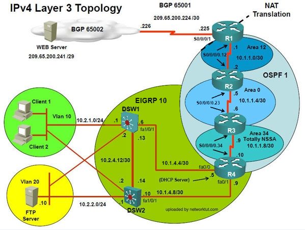
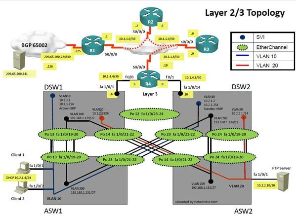
Topology Overview (Actual Troubleshooting lab design is for below network design)
Client Should have IP 10.2.1.3
EIGRP 100 is running between switch DSW1 & DSW2
OSPF (Process ID 1) is running between R1, R2, R3, R4
Network of OSPF is redistributed in EIGRP
BGP 65001 is configured on R1 with Webserver cloud AS 65002
HSRP is running between DSW1 & DSW2 Switches
The company has created the test bed shown in the layer 2 and layer 3 topology exhibits.
This network consists of four routers, two layer 3 switches and two layer 2 switches.
In the IPv4 layer 3 topology, R1, R2, R3, and R4 are running OSPF with an OSPF process
number 1.
DSW1, DSW2 and R4 are running EIGRP with an AS of 10. Redistribution is enabled where
necessary.
R1 is running a BGP AS with a number of 65001. This AS has an eBGP connection to AS 65002
in the ISP’s network. Because the company’s address space is in the private range.
R1 is also providing NAT translations between the inside (10.1.0.0/16 & 10.2.0.0/16) networks and
outside (209.65.0.0/24) network.
ASW1 and ASW2 are layer 2 switches.
NTP is enabled on all devices with 209.65.200.226 serving as the master clock source.
The client workstations receive their IP address and default gateway via R4’s DHCP server.
The default gateway address of 10.2.1.254 is the IP address of HSRP group 10 which is running
on DSW1 and DSW2.
In the IPv6 layer 3 topology R1, R2, and R3 are running OSPFv3 with an OSPF process number
6.
DSW1, DSW2 and R4 are running RIPng process name RIP_ZONE.
The two IPv6 routing domains, OSPF 6 and RIPng are connected via GRE tunnel running over the
underlying IPv4 OSPF domain. Redistrution is enabled where necessary.
Recently the implementation group has been using the test bed to do a ‘proof-of-concept’ on
several implementations. This involved changing the configuration on one or more of the devices.
You will be presented with a series of trouble tickets related to issues introduced during these
configurations.
Note: Although trouble tickets have many similar fault indications, each ticket has its own issue
and solution.
Each ticket has 3 sub questions that need to be answered & topology remains same.
Question-1Fault is found on which device,
Question-2Fault condition is related to,
Question-3What exact problem is seen & what needs to be done for solution
==========================================================================
-Client is unable to ping IP 209.65.200.241
Solution
Steps need to follow as below:-When we check on client 1 & Client 2 desktop we are not receiving DHCP address from R4
—Ipconfig —– Client will be getting 169.X.X.X
On ASW1 port Fa1/0/ 1 & Fa1/0/2 access port VLAN 10 was assigned which is using IP address
10.2.1.0/24
Sh run ——- & check for running config of int fa1/0/1 & fa1/0/2
====================================================
interface FastEthernet1/0/1switchport mode accessswitchport access vlan 10interface
FastEthernet1/0/2switchport mode accessswitchport access vlan 10
====================================================
We need to check on ASW 1 trunk port the trunk Po13 & Po23 were receiving VLAN 20 & 200
but not VLAN 10 so that switch could not get DHCP IP address and was failing to reach IP
address of Internet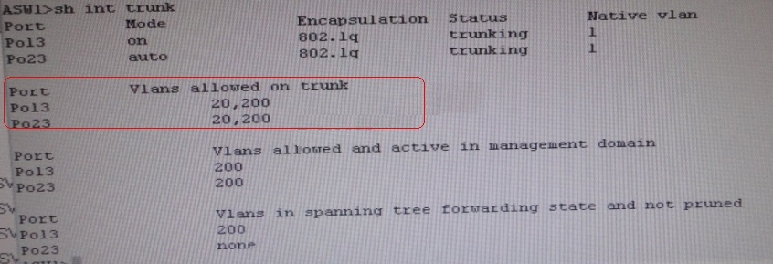
Change required: On ASW1 below change is required for switch-to-switch connectivity..
int range portchannel13,portchannel23 switchport trunk allowed vlan none switchport trunk
allowed vlan 10,200
———————————————————-
So in ticket Answer to the fault condition will be as :
The implementations group has been using the test bed to do a ‘proof-of-concept’ that
requires both Client 1 and Client 2 to access the WEB Server at 209.65.200.241. After
several changes to the network addressing, routing scheme, DHCP services, NTP services,
and FHRP services, a trouble ticket has been operated indicating that Client 1 cannot ping
the 209.65.200.241 address.
Use the supported commands to Isolated the cause of this fault and answer the following
questions.
On which device is the fault condition located?
which technology?
Topology Overview (Actual Troubleshooting lab design is for below network design)
Client Should have IP 10.2.1.3
EIGRP 100 is running between switch DSW1 & DSW2
OSPF (Process ID 1) is running between R1, R2, R3, R4
Network of OSPF is redistributed in EIGRP
BGP 65001 is configured on R1 with Webserver cloud AS 65002
HSRP is running between DSW1 & DSW2 Switches
The company has created the test bed shown in the layer 2 and layer 3 topology exhibits.
This network consists of four routers, two layer 3 switches and two layer 2 switches.
In the IPv4 layer 3 topology, R1, R2, R3, and R4 are running OSPF with an OSPF process
number 1.
DSW1, DSW2 and R4 are running EIGRP with an AS of 10. Redistribution is enabled where
necessary.
R1 is running a BGP AS with a number of 65001. This AS has an eBGP connection to AS 65002
in the ISP’s network. Because the company’s address space is in the private range.
R1 is also providing NAT translations between the inside (10.1.0.0/16 & 10.2.0.0/16) networks and
outside (209.65.0.0/24) network.
ASW1 and ASW2 are layer 2 switches.
NTP is enabled on all devices with 209.65.200.226 serving as the master clock source.
The client workstations receive their IP address and default gateway via R4’s DHCP server.
The default gateway address of 10.2.1.254 is the IP address of HSRP group 10 which is running
on DSW1 and DSW2.
In the IPv6 layer 3 topology R1, R2, and R3 are running OSPFv3 with an OSPF process number
6.
DSW1, DSW2 and R4 are running RIPng process name RIP_ZONE.
The two IPv6 routing domains, OSPF 6 and RIPng are connected via GRE tunnel running over the
underlying IPv4 OSPF domain. Redistrution is enabled where necessary.
Recently the implementation group has been using the test bed to do a ‘proof-of-concept’ on
several implementations. This involved changing the configuration on one or more of the devices.
You will be presented with a series of trouble tickets related to issues introduced during these
configurations.
Note: Although trouble tickets have many similar fault indications, each ticket has its own issue
and solution.
Each ticket has 3 sub questions that need to be answered & topology remains same.
Question-1Fault is found on which device,
Question-2Fault condition is related to,
Question-3What exact problem is seen & what needs to be done for solution
==========================================================================
-Client is unable to ping IP 209.65.200.241
Solution
Steps need to follow as below:-When we check on client 1 & Client 2 desktop we are not receiving DHCP address from R4
—Ipconfig —– Client will be getting 169.X.X.X
On ASW1 port Fa1/0/ 1 & Fa1/0/2 access port VLAN 10 was assigned which is using IP address
10.2.1.0/24
Sh run ——- & check for running config of int fa1/0/1 & fa1/0/2
====================================================
interface FastEthernet1/0/1switchport mode accessswitchport access vlan 10interface
FastEthernet1/0/2switchport mode accessswitchport access vlan 10
====================================================
We need to check on ASW 1 trunk port the trunk Po13 & Po23 were receiving VLAN 20 & 200
but not VLAN 10 so that switch could not get DHCP IP address and was failing to reach IP
address of Internet
Change required: On ASW1 below change is required for switch-to-switch connectivity..
int range portchannel13,portchannel23 switchport trunk allowed vlan none switchport trunk
allowed vlan 10,200
———————————————————-
So in ticket Answer to the fault condition will be as :
The implementations group has been using the test bed to do a ‘proof-of-concept’ that
requires both Client 1 and Client 2 to access the WEB Server at 209.65.200.241. After
several changes to the network addressing, routing scheme, DHCP services, NTP services,
and FHRP services, a trouble ticket has been opened indicating that Client 1 cannot ping
the 209.65.200.241 address.
Use the supported commands to isolated the cause of this fault and answer the following
questions.
The fault condition is related to which technology?
What is the solution to the fault condition?
Topology Overview (Actual Troubleshooting lab design is for below network design)
Client Should have IP 10.2.1.3
EIGRP 100 is running between switch DSW1 & DSW2
OSPF (Process ID 1) is running between R1, R2, R3, R4
Network of OSPF is redistributed in EIGRP
BGP 65001 is configured on R1 with Webserver cloud AS 65002
HSRP is running between DSW1 & DSW2 Switches
The company has created the test bed shown in the layer 2 and layer 3 topology exhibits.
This network consists of four routers, two layer 3 switches and two layer 2 switches.
In the IPv4 layer 3 topology, R1, R2, R3, and R4 are running OSPF with an OSPF process
number 1.
DSW1, DSW2 and R4 are running EIGRP with an AS of 10. Redistribution is enabled where
necessary.
R1 is running a BGP AS with a number of 65001. This AS has an eBGP connection to AS 65002
in the ISP’s network. Because the company’s address space is in the private range.
R1 is also providing NAT translations between the inside (10.1.0.0/16 & 10.2.0.0/16) networks and
outside (209.65.0.0/24) network.
ASW1 and ASW2 are layer 2 switches.
NTP is enabled on all devices with 209.65.200.226 serving as the master clock source.
The client workstations receive their IP address and default gateway via R4’s DHCP server.
The default gateway address of 10.2.1.254 is the IP address of HSRP group 10 which is running
on DSW1 and DSW2.
In the IPv6 layer 3 topology R1, R2, and R3 are running OSPFv3 with an OSPF process number
6.
DSW1, DSW2 and R4 are running RIPng process name RIP_ZONE.
The two IPv6 routing domains, OSPF 6 and RIPng are connected via GRE tunnel running over the
underlying IPv4 OSPF domain. Redistrution is enabled where necessary.
Recently the implementation group has been using the test bed to do a ‘proof-of-concept’ on
several implementations. This involved changing the configuration on one or more of the devices.
You will be presented with a series of trouble tickets related to issues introduced during these
configurations.
Note: Although trouble tickets have many similar fault indications, each ticket has its own issue
and solution.
Each ticket has 3 sub questions that need to be answered & topology remains same.
Question-1Fault is found on which device,
Question-2Fault condition is related to,
Question-3What exact problem is seen & what needs to be done for solution
==========================================================================
-Client is unable to ping IP 209.65.200.241
Solution
Steps need to follow as below:-When we check on client 1 & Client 2 desktop we are not receiving DHCP address from R4
—Ipconfig —– Client will be getting 169.X.X.X
On ASW1 port Fa1/0/ 1 & Fa1/0/2 access port VLAN 10 was assigned which is using IP address
10.2.1.0/24
Sh run ——- & check for running config of int fa1/0/1 & fa1/0/2
====================================================
interface FastEthernet1/0/1switchport mode accessswitchport access vlan 10interface
FastEthernet1/0/2switchport mode accessswitchport access vlan 10
====================================================
We need to check on ASW 1 trunk port the trunk Po13 & Po23 were receiving VLAN 20 & 200
but not VLAN 10 so that switch could not get DHCP IP address and was failing to reach IP
address of Internet
Change required: On ASW1 below change is required for switch-to-switch connectivity..
int range portchannel13,portchannel23 switchport trunk allowed vlan none switchport trunk
allowed vlan 10,200
———————————————————-
So in ticket Answer to the fault condition will be as :
The implementations group has been using the test bed to do a ‘proof-of-concept’ that
requires both Client 1 and Client 2 to access the WEB Server at 209.65.200.241. After
several changes to the network addressing, routing scheme, DHCP services, NTP services,
and FHRP services, a trouble ticket has been opened indicating that Client 1 cannot ping
the 209.65.200.241 address.
Use the supported commands to isolated the cause of this fault and answer the following
questions.
What is the solution to the fault condition?