

DRAG DROP
Match the items on the left to their purpose on the right.

Answer: 
Explanation:
EEM -> CLI based Management and Monitoring
SDM -> Provides a GUI for Administration
FTP -> Used for Backup and Restore
Cisco IOS Embedded Event Manager (EEM) is a powerful and flexible CLI based subsystem that
provides real-time network event detection and onboard automation. It gives you the ability to
adapt the behavior of your network devices to align with your business needs.
Cisco SDM is an intuitive, Web-based device-management tool for Cisco IOS® Software-based
routers. The Cisco SDM simplifies router and security configuration through smart wizards, which
help customers and Cisco partners quickly and easily deploy, configure, and monitor a Cisco router
without requiring knowledge of the command-line interface (CLI). The Cisco SDM is supported on a
wide range of Cisco routers and Cisco IOS Software releases.
Cisco devices can use FTP to backup and restore configuration files and IOS software. Some
examples of this are shown below:
Example 1: Backing up manually
R1# copy startup-config ftp://kevin:dj7jS@192.168.22.33
Address or name of remote host [ 192.168.22.33]?
Destination file name [r1-confg]?
Writing R1-confg !!!
3458 bytes copied in 3.443 secs (1243 bytes/sec)
Example 2: Backing up automatically
The configuration below will make a backup:
write-memory Trigger backup when running-config is copied to nvram
time-period 1440 Trigger backup every 1440 minuttes. 60*24=1440
!
ip ftp username kevin
ip ftp password dj7jS
!
archive
path ftp://192.168.2.33/R1-config
write-memory
time-period 1440Viewing
R1#show archive
The next archive file will be named ftp://192.168.2.33/R1-confg-4
Archive # Name
0
1 ftp://192.168.2.33/R1-confg-1
2 ftp://192.168.2.33/R1-confg-2
3 ftp://192.168.2.33/R1-confg-3 <- Most RecentTicket 1 : Switch Port Trunk
Topology Overview (Actual Troubleshooting lab design is for below network design)
Client Should have IP 10.2.1.3
EIGRP 100 is running between switch DSW1 & DSW2
OSPF (Process ID 1) is running between R1, R2, R3, R4
Network of OSPF is redistributed in EIGRP
BGP 65001 is configured on R1 with Webserver cloud AS 65002
HSRP is running between DSW1 & DSW2 Switches
The company has created the test bed shown in the layer 2 and layer 3 topology exhibits.
This network consists of four routers, two layer 3 switches and two layer 2 switches.
In the IPv4 layer 3 topology, R1, R2, R3, and R4 are running OSPF with an OSPF process number 1.
DSW1, DSW2 and R4 are running EIGRP with an AS of 10. Redistribution is enabled where necessary.
R1 is running a BGP AS with a number of 65001. This AS has an eBGP connection to AS 65002 in the
ISP’s network. Because the company’s address space is in the private range.
R1 is also providing NAT translations between the inside (10.1.0.0/16 & 10.2.0.0/16) networks and
outside (209.65.0.0/24) network.
ASW1 and ASW2 are layer 2 switches.
NTP is enabled on all devices with 209.65.200.226 serving as the master clock source.
The client workstations receive their IP address and default gateway via R4’s DHCP server.
The default gateway address of 10.2.1.254 is the IP address of HSRP group 10 which is running on
DSW1 and DSW2.
In the IPv6 layer 3 topology R1, R2, and R3 are running OSPFv3 with an OSPF process number 6.
DSW1, DSW2 and R4 are running RIPng process name RIP_ZONE.
The two IPv6 routing domains, OSPF 6 and RIPng are connected via GRE tunnel running over the
underlying IPv4 OSPF domain. Redistrution is enabled where necessary.
Recently the implementation group has been using the test bed to do a ‘proof-of-concept’ on several
implementations. This involved changing the configuration on one or more of the devices. You will
be presented with a series of trouble tickets related to issues introduced during these
configurations.
Note: Although trouble tickets have many similar fault indications, each ticket has its own issue and
solution.
Each ticket has 3 sub questions that need to be answered & topology remains same.
Question-1 Fault is found on which device,
Question-2 Fault condition is related to,
Question-3 What exact problem is seen & what needs to be done for solution
===============================================================================
Client is unable to ping IP 209.65.200.241
Solution
Steps need to follow as below:-
1. When we check on client 1 & Client 2 desktop we are not receiving DHCP address from R4
Ipconfig —– Client will be getting 169.X.X.X
2. On ASW1 port Fa1/0/ 1 & Fa1/0/2 access port VLAN 10 was assigned which is using IP
address 10.2.1.0/24
Sh run ——- & check for running config of int fa1/0/1 & fa1/0/2
====================================================
interface FastEthernet1/0/1
switchport mode access
switchport access vlan 10
interface FastEthernet1/0/2
switchport mode access
switchport access vlan 10
====================================================
3. We need to check on ASW 1 trunk port the trunk Po13 & Po23 were receiving VLAN 20 &
200 but not VLAN 10 so that switch could not get DHCP IP address and was failing to reach IP
address of Internet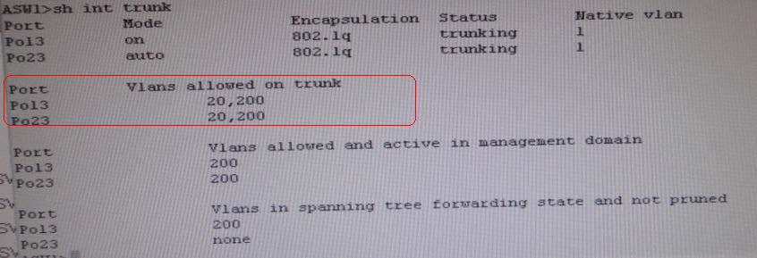
1. Change required: On ASW1 below change is required for switch-to-switch connectivity.. int
range portchannel13,portchannel23
switchport trunk allowed vlan none
switchport trunk allowed vlan 10,200
——————————————————————————————————————————
So in ticket Answer to the fault condition will be as :


