

###BeginTicket2###
Ticket 2 : ACCESS VLAN
Topology Overview (Actual Troubleshooting lab design is for below network design)
——
Client Should have IP 10.2.1.3
EIGRP 100 is running between switch DSW1 & DSW2
OSPF (Process ID 1) is running between R1, R2, R3, R4
Network of OSPF is redistributed in EIGRP
BGP 65001 is configured on R1 with Webserver cloud AS 65002
HSRP is running between DSW1 & DSW2 Switches
The company has created the test bed shown in the layer 2 and layer 3 topology exhibits.
This network consists of four routers, two layer 3 switches and two layer 2 switches.
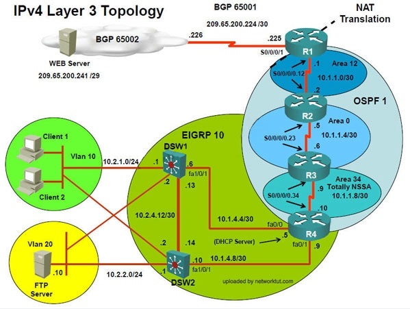
In the IPv4 layer 3 topology, R1, R2, R3, and R4 are running OSPF with an OSPF process
number 1.
DSW1, DSW2 and R4 are running EIGRP with an AS of 10. Redistribution is enabled where
necessary.
R1 is running a BGP AS with a number of 65001. This AS has an eBGP connection to AS 65002
in the ISP’s network. Because the company’s address space is in the private range.
R1 is also providing NAT translations between the inside (10.1.0.0/16 & 10.2.0.0/16) networks and
outside (209.65.0.0/24) network.
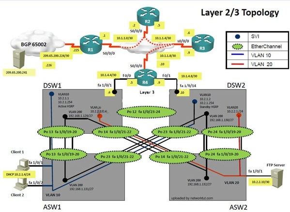
ASW1 and ASW2 are layer 2 switches.
NTP is enabled on all devices with 209.65.200.226 serving as the master clock source.
The client workstations receive their IP address and default gateway via R4’s DHCP server.
The default gateway address of 10.2.1.254 is the IP address of HSRP group 10 which is running
on DSW1 and DSW2.
In the IPv6 layer 3 topology R1, R2, and R3 are running OSPFv3 with an OSPF process number 6.
DSW1, DSW2 and R4 are running RIPng process name RIP_ZONE.
The two IPv6 routing domains, OSPF 6 and RIPng are connected via GRE tunnel running over the
underlying IPv4 OSPF domain. Redistrution is enabled where necessary.
Recently the implementation group has been using the test bed to do a ‘proof-of-concept’ on
several implementations. This involved changing the configuration on one or more of the devices.
You will be presented with a series of trouble tickets related to issues introduced during these
configurations.
Note: Although trouble tickets have many similar fault indications, each ticket has its own issue
and solution.
Each ticket has 3 sub questions that need to be answered & topology remains same.
Question-1 Fault is found on which device,
Question-2 Fault condition is related to,
Question-3 What exact problem is seen & what needs to be done for solution
– – —
Client is unable to ping IP 209.65.200.241
Solution
Steps need to follow as below:-
When we check on client 1 & Client 2 desktop we are not receiving DHCP address from R4
Ipconfig —– Client will be getting 169.X.X.X
On ASW1 port Fa1/0/ 1 & Fa1/0/2 access port VLAN 10 was assigned which is using IP address
10.2.1.0/24
Sh run ——- & check for running config of int fa1/0/1 & fa1/0/2
====================================================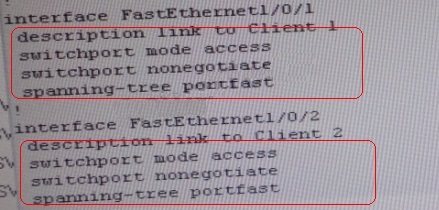
====================================================
Here we are not able to see access Vlan10 configured for Port Fa1/0/1 & Fa1/0/2
Change required: On ASW1, for configuring Access Vlan under interface fa1/0/1 & 1/0/2 we
have to enable command switchport access vlan 10
###EndTicket2###
The implementations group has been using the test bed to do a ‘proof-of-concept’ that
requires both Client 1 and Client 2 to access the WEB Server at 209.65.200.241. After
several changes to the network addressing, routing scheme, DHCP services, NTP services,
layer 2 connectivity, FHRP services, and device security, a trouble ticket has been opened
indicating that Client 1 cannot ping the 209.65.200.241 address.
Use the supported commands to isolated the cause of this fault and answer the following
questions.
What is the solution to the fault condition?

A.
R1
B.
R2
C.
R3
D.
R4
E.
DSW1
F.
DSW2
G.
ASW1
H.
ASW2
Explanation:
The problem here is that VLAN 10 is not configured on the proper interfaces on switch ASW1.