
Drag the Frame Relay acronym on the left to match its definition on the right.
DRAG DROP
Drag the Frame Relay acronym on the left to match its definition on the right. (Not all acronyms
are used.)

Drag each destination IP address on the left to its correct next hop address on the right.
DRAG DROP
Drag each destination IP address on the left to its correct next hop address on the right.

Drag the term on the left to its definition on the right.
DRAG DROP
Drag the term on the left to its definition on the right.

Drag the term on the left to its definition on the right.
DRAG DROP
Drag the term on the left to its definition on the right.

Drag the appropriate 5 steps of the boot sequence on the left to their correct slots on the right.
DRAG DROP
Drag the appropriate 5 steps of the boot sequence on the left to their correct slots on the right.

From the partial router output below, match the output information to the OSI layer.
DRAG DROP
From the partial router output below, match the output information to the OSI layer.

Drag the description on the left to the correct router mode on right.
DRAG DROP
Drag the description on the left to the correct router mode on right.

Drag the description on the left to the routing protocol on the right.
DRAG DROP
Drag the description on the left to the routing protocol on the right.

Complete the network topology shown in the graphic by dragging the labels below with the appropriate router ty
DRAG DROP
Complete the network topology shown in the graphic by dragging the labels below with the appropriate router types, interface types, and IP addresses to the graphic


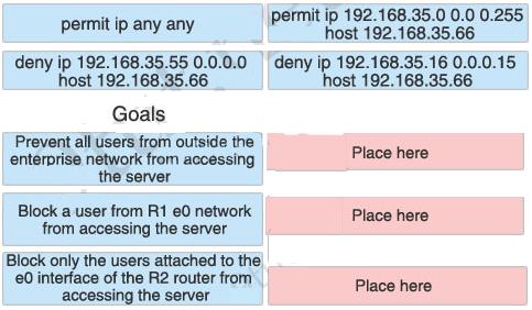
Drag the boxes on the top to complete the goal on the left.
DRAG DROP
Two offices are displayed below

You work as a network technician. Study the exhibit carefully. The company has a main office in
Los Angeles and a satellite office in Boston. The offices are connected through two Cisco routers.
The Boston satellite office is connected through the R2 router s0 interface to the Los Angeles
office R1 router s1 interface. R1 has two local area networks. Boston users receive Internet
access through the R1 router. Drag the boxes on the top to complete the goal on the left.