

You want to configure a redundant trunk group on a switch. You want ge-0/0/0.0 to be the default link; however, if ge-0/0/0.0 fails and the switch begins using ge-0/0/1.0, you want the switch to continue using ge-0/0/1.0 until ge-0/0/1.0 fails.
Which configuration will accomplish this scenario?

A.
redundant-trunk-group {
interface ge-0/0/0.0 {
primary;
}
interface ge-0/0/1.0 {
primary;
}
}
B.
redundant-trunk-group {
interface ge-0/0/0.0;
interface ge-0/0/1.0;
no-preempt;
}
C.
redundant-trunk-group {
interface ge-0/0/0.0 {
primary;
}
interface ge-0/0/1.0;
}
D.
redundant-trunk-group {
interface ge-0/0/0.0;
interface ge-0/0/1.0;
}
Explanation:
Understanding Redundant Trunk Links on EX Series SwitchesIn a typical enterprise network comprised of distribution and access layers, a redundant trunk link provides a simple solution for network recovery when a trunk port on a Juniper Networks EX Series Ethernet Switch goes down. In that case, traffic is routed to another trunk port, keeping network convergence time to a minimum. You can configure a maximum of 16 redundant trunk groups on a standalone switch or on a Virtual Chassis.
To configure a redundant trunk link, create a redundant trunk group. The redundant trunk group is configured on the access switch, and contains two links: a primary or active link, and a secondary link. If the active link fails, the secondary link automatically starts forwarding data traffic without waiting for normal spanning-tree protocol convergence.
Data traffic is forwarded only on the active link. Data traffic on the secondary link is dropped and shown as dropped packets when you issue the operational mode command show interfaces xe- xe-fpc/pic/port extensive.
While data traffic is blocked on the secondary link, Layer 2 control traffic is still permitted. For example, an LLDP session can be run between two switches on the secondary link.
Rapid Spanning Tree Protocol (RSTP) is enabled by default on EX Series switches to create a loop-free topology, but an interface is not allowed to be in both a redundant trunk group and in a spanning-tree protocol topology at the same time. You must disable RSTP on an interface if a redundant trunk group is configured on that interface. For example, in Figure 1, in addition to disabling RSTP on the Switch 3 interfaces, you must also disable RSTP on the Switch 1 and Switch 2 interfaces connected to Switch 3. Spanning-tree protocols can, however, continue operating on other interfaces on those switches, for example on the link between Switch 1 and Switch 2.
Figure 1 shows three switches in a basic topology for redundant trunk links. Switch 1 and Switch 2 make up the distribution layer, and Switch 3 makes up the access layer. Switch 3 is connected to the distribution layer through trunk ports ge-0/0/9.0 (Link 1) and ge-0/0/10.0 (Link 2). Link 1 and Link 2 are in a redundant trunk group called group1. Link 1 is designated as the primary link. Traffic flows between Switch 3 in the access layer and Switch 1 in the distribution layer through Link 1. While Link 1 is active, Link 2 blocks traffic.
Figure 1: Redundant Trunk Group, Link 1 Active
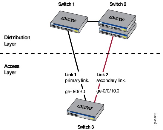
Figure 2 illustrates how the redundant trunk link topology works when the primary link goes down.
Figure 2: Redundant Trunk Group, Link 2 Active
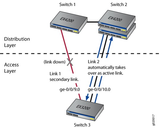
When Link 1 goes down between Switch 3 and Switch 1, Link 2 takes over as the active link after one second.
Traffic between the access layer and the distribution layer is then automatically switched to Link 2 between Switch 1 and Switch 2.

