

Configure the Multilayer Switch so that PCs from VLAN 2 and VLAN 3 can communicate with the Server.
MLS and EIGRP Sim 1
Configure the Multilayer Switch so that PCs from VLAN 2 and VLAN 3 can communicate with the Server.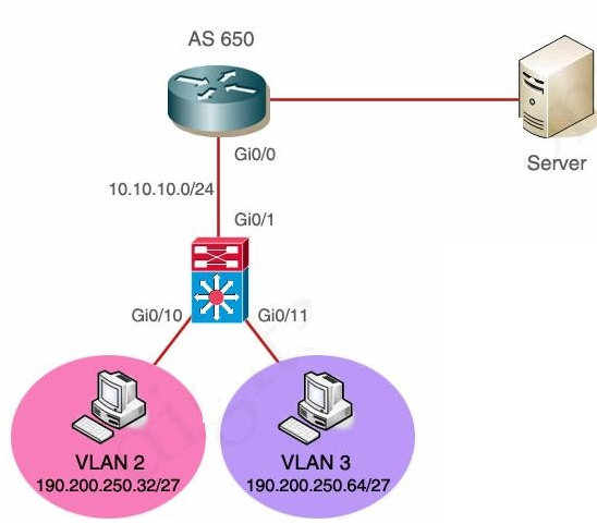
You need to configure SwitchC so that Hosts H1 and H2 can successful ping the server S1
MLS and EIGRP Sim 2
You have been tasked with configuring multilayer SwitchC, which has a partial configuration and has been
attached to RouterC as shown in the topology diagram.
You need to configure SwitchC so that Hosts H1 and H2 can successful ping the server S1. Also SwitchC
needs to be able to ping server S1.
Due to administrative restrictions and requirementsyou should not add/delete vlans, changes VLAN port
assignments or create trunk links
Company policies forbid the use of static or default routing All routes must be learned via EIGRP 65010 routing
protocol.
You do not have access to RouteC, RouterC is correctly configured. No trunking has been configured on
RouterC.
Routed interfaces should use the lowest host on a subnet when possible. The following subnets are available to
implement this solution:
· 172.16.1.0/24
· 192.168.3.32/27
· 192.168.3.64/27
Hosts H1 and H2 are configured with the correct IP address and default gateway.
SwitchC uses Cisco as the enable password.
Routing must only be enabled for the specific subnets shown in the diagram.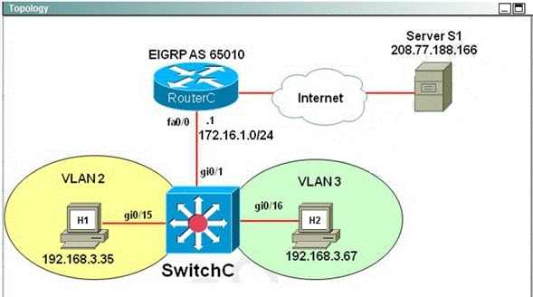
Host1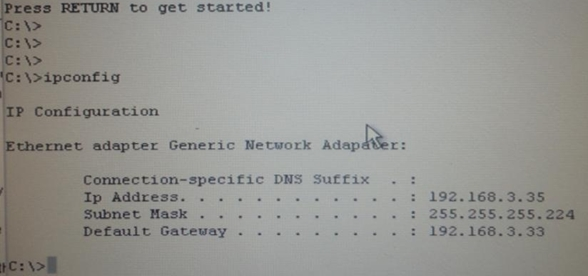
Host 2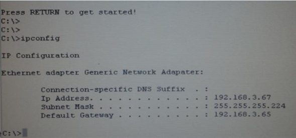
You are required to accomplishthe following tasks…
STP Lab Sim
The information of the question
You will configure FastEthernet ports 0/12 through 0/24 for users who belong to VLAN 20. Also, all VLAN and
VTP configurations are to be completed in global configuration mode as VLAN database mode is being
deprecated by Cisco. You are required to accomplishthe following tasks:
1. Ensure the switch does not participate in VTP but forwards VTP advertisements received on trunk ports.
2. Ensure all non-trunking interfaces (Fa0/1 to Fa0/24) transition immediately to the forwarding stateof
Spanning-Tree.
3. Ensure all FastEthernet interfaces are in a permanent non-trunking mode.
4. Place FastEthernet interfaces 0/12 through 0/24 in VLAN 20
Make switch B the root
LACP with STP 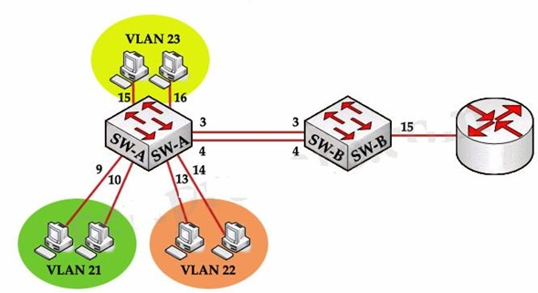
Each of these vlans has one host each on its ports
SVI on vlan 1 – ip 192.168.1.11
Switch B -Ports 3, 4 connected to ports 3 and 4 on Switch A
Port 15 connected to Port on Router.
Tasks to do:
1. Use non proprietary mode of aggregation with Switch B being the initiator
— Use LACP with B being in Active mode
2. Use non proprietary trunking and no negotiation
— Use switchport mode trunk and switchport trunk encapsulation dot1q
3. Restrict only to the VLANs needed
— Use either VTP pruning or allowed VLAN list. Thepreferred method is using allowed VLAN list
4. SVI on VLAN 1 with some ip and subnet given
5. Configure switch A so that nodes other side of Router C are accessible
— on switch A the default gateway has to be configured.
6. Make switch B the root
You have been tasked with implementing the above access control as a pre-condition to installing the servers.
AAAdot1x Lab Sim
Acme is a small shipping company that has an existing enterprise network comprised of 2 switches DSW1 and
ASW2. The topology diagram indicates their layer 2 mapping. VLAN 40 is a new VLAN that will be used to
provide the shipping personnel access to the server. For security reasons, it is necessary to restrictaccess to
VLAN 20 in the following manner:
– Users connecting to ASW1’s port must be authenticate before they are given access to the network.
– Authentication is to be done via a Radius server:
– Radius server host: 172.120.39.46
– Radius key: rad123
– Authentication should be implemented as close to the host device possible.
– Devices on VLAN 20 are restricted to in the address range of 172.120.40.0/24.
– Packets from devices in the address range of 172.120.40.0/24 should be passed on VLAN 20.
– Packets from devices in any other address range should be dropped on VLAN 20.
– Filtering should be implemented as close to the server farm as possible.
The Radius server and application servers will be installed at a future date. You have been tasked with
implementing the above access control as a pre-condition to installing the servers.
You must use the available IOS switch features.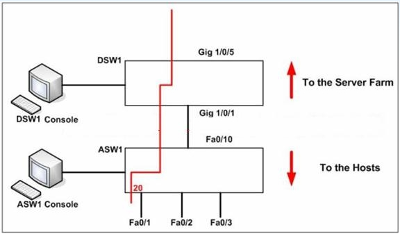
· SwitchB VTP mode needs to be the same as Switch
LACP with STP Sim 2
You work for SWITCH.com. They have just added a newswitch (SwitchB) to the existing network as shown in
the topology diagram.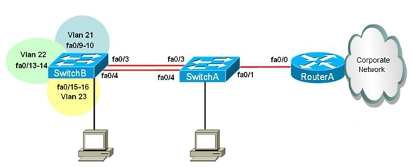
RouterA is currently configured correctly and is providing the routing function for devices on SwitchAand
SwitchB. SwitchA is currently configured correctly,but will need to be modified to support the addition of
SwitchB. SwitchB has a minimal configuration. You have been tasked with competing the configuration of
SwitchA and SwitchB. SwitchA and SwitchB use Cisco as the enable password.
Configuration Requirements for SwitchA
The VTP and STP configuration modes on SwitchA should not be modified.
Steps
· SwitchA needs to be the root switch for vlans 11,12, 13, 21, 22 and 23. All other vlans should be left are their
default values.
Configuration Requirements for SwitchB
– Vlan 21, Name: Marketing, will support two servers attached to fa0/9 and fa0/10
– Vlan 22, Name: Sales, will support two servers attached to fa0/13 and fa0/14
– Vlan 23, Name: Engineering, will support two servers attached to fa0/15 and fa0/16
· Access ports that connect to server should transition immediately to forwarding state upon detectingthe
connection of a device.
· SwitchB VTP mode needs to be the same as SwitchA.
· SwitchB must operate in the same spanning tree mode as SwitchA
· No routing is to be configured on SwitchB
· Only the SVI vlan 1 is to be configured and it isto use address 192.168.1.11/24
Inter-switch Connectivity Configuration Requirements:
· For operational and security reasons trunking should be unconditional and Vlans 1, 21, 22 and 23 should
tagged when traversing the trunk link.
· The two trunks between SwitchA and SwitchB need to be configured in a mode that allows for the maximum
use of their bandwidth for all vlans. This mode should be done with a non- proprietary protocol, with SwitchA
controlling activation.
· Propagation of unnecessary broadcasts should be limited using manual pruning on this trunk link.