

What is the solution to the fault condition?
###BeginTicket7###
Ticket 7 : Port Security
Topology Overview (Actual Troubleshooting lab design is for below network design)
Client Should have IP 10.2.1.3
EIGRP 100 is running between switch DSW1 & DSW2
OSPF (Process ID 1) is running between R1, R2, R3, R4
Network of OSPF is redistributed in EIGRP
BGP 65001 is configured on R1 with Webserver cloud AS 65002
HSRP is running between DSW1 & DSW2 Switches
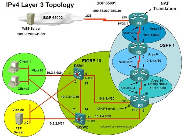
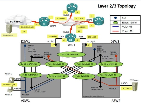
The company has created the test bed shown in the layer 2 and layer 3 topology exhibits.
This network consists of four routers, two layer 3 switches and two layer 2 switches.
In the IPv4 layer 3 topology, R1, R2, R3, and R4 are running OSPF with an OSPF process
number 1.
DSW1, DSW2 and R4 are running EIGRP with an AS of 10. Redistribution is enabled where
necessary.
R1 is running a BGP AS with a number of 65001. This AS has an eBGP connection to AS 65002
in the ISP’s network. Because the company’s address space is in the private range.
R1 is also providing NAT translations between the inside (10.1.0.0/16 & 10.2.0.0/16) networks and
outside (209.65.0.0/24) network.
ASW1 and ASW2 are layer 2 switches.
NTP is enabled on all devices with 209.65.200.226 serving as the master clock source.
The client workstations receive their IP address and default gateway via R4’s DHCP server.
The default gateway address of 10.2.1.254 is the IP address of HSRP group 10 which is running
on DSW1 and DSW2.
In the IPv6 layer 3 topology R1, R2, and R3 are running OSPFv3 with an OSPF process number 6.
DSW1, DSW2 and R4 are running RIPng process name RIP_ZONE.
The two IPv6 routing domains, OSPF 6 and RIPng are connected via GRE tunnel running over the
underlying IPv4 OSPF domain. Redistrution is enabled where necessary.
Recently the implementation group has been using the test bed to do a ‘proof-of-concept’ on
several implementations. This involved changing the configuration on one or more of the devices.
You will be presented with a series of trouble tickets related to issues introduced during these
configurations.
Note: Although trouble tickets have many similar fault indications, each ticket has its own issue
and solution.
Each ticket has 3 sub questions that need to be answered & topology remains same.
Question-1 Fault is found on which device,
Question-2 Fault condition is related to,
Question-3 What exact problem is seen & what needs to be done for solution


– –
Client is unable to ping IP 209.65.200.241
Solution
Steps need to follow as below:-
When we check on client 1 & Client 2 desktop we are not receiving DHCP address from R4
ipconfig —– Client will be getting 169.X.X.X
On ASW1 port Fa1/0/ 1 & Fa1/0/2 access port VLAN 10 was assigned but when we checked
interface it was showing down
Sh run ——- check for running config of int fa1/0/1 & fa1/0/2 (switchport access Vlan 10 will be
there with switch
port security command). Now check as below
Sh int fa1/0/1 & sh int fa1/0/2

– –
As seen on interface the port is in err-disable mode so need to clear port.
Change required: On ASW1, we need to remove port-security under interface fa1/0/1 & fa1/0/2.
——————————————————————————————————————————
###EndTicket7###
The implementations group has been using the test bed to do a ‘proof-of-concept’ that
requires both Client 1 and Client 2 to access the WEB Server at 209.65.200.241. After
several changes to the network addressing, routing scheme, DHCP services, NTP services,
layer 2 connectivity, FHRP services, and device security, a trouble ticket has been opened
indicating that Client 1 cannot ping the 209.65.200.241 address.
Use the supported commands to isolated the cause of this fault and answer the following
questions.
What is the solution to the fault condition?
which device is the fault condition located?
###BeginTicket8###
Ticket 8 : Redistribution of EIGRP to OSPF
Topology Overview (Actual Troubleshooting lab design is for below network design)
Client Should have IP 10.2.1.3
EIGRP 100 is running between switch DSW1 & DSW2
OSPF (Process ID 1) is running between R1, R2, R3, R4
Network of OSPF is redistributed in EIGRP
BGP 65001 is configured on R1 with Webserver cloud AS 65002
HSRP is running between DSW1 & DSW2 Switches
The company has created the test bed shown in the layer 2 and layer 3 topology exhibits.
This network consists of four routers, two layer 3 switches and two layer 2 switches.
In the IPv4 layer 3 topology, R1, R2, R3, and R4 are running OSPF with an OSPF process
number 1.
DSW1, DSW2 and R4 are running EIGRP with an AS of 10. Redistribution is enabled where
necessary.
R1 is running a BGP AS with a number of 65001. This AS has an eBGP connection to AS 65002
in the ISP’s network. Because the company’s address space is in the private range.
R1 is also providing NAT translations between the inside (10.1.0.0/16 & 10.2.0.0/16) networks and
outside (209.65.0.0/24) network.
ASW1 and ASW2 are layer 2 switches.
NTP is enabled on all devices with 209.65.200.226 serving as the master clock source.
The client workstations receive their IP address and default gateway via R4’s DHCP server.
The default gateway address of 10.2.1.254 is the IP address of HSRP group 10 which is running
on DSW1 and DSW2.
In the IPv6 layer 3 topology R1, R2, and R3 are running OSPFv3 with an OSPF process number 6.
DSW1, DSW2 and R4 are running RIPng process name RIP_ZONE.
The two IPv6 routing domains, OSPF 6 and RIPng are connected via GRE tunnel running over the
underlying IPv4 OSPF domain. Redistrution is enabled where necessary.
Recently the implementation group has been using the test bed to do a ‘proof-of-concept’ on
several implementations. This involved changing the configuration on one or more of the devices.
You will be presented with a series of trouble tickets related to issues introduced during these
configurations.
Note: Although trouble tickets have many similar fault indications, each ticket has its own issue
and solution.
Each ticket has 3 sub questions that need to be answered & topology remains same.
Question-1 Fault is found on which device,
Question-2 Fault condition is related to,
Question-3 What exact problem is seen & what needs to be done for solution


Client is unable to ping IP 209.65.200.241
Solution
Steps need to follow as below:-
When we check on client 1 & Client 2 desktop we are not receiving DHCP address from R4
– – – – – –
ipconfig —– Client will be receiving IP address 10.2.1.3
IP 10.2.1.3 will be able to ping from R4 , but cannot ping from R3, R2, R1
This clearly shows problem at R4 since EIGRP is between DSW1, DSW2 & R4 and OSPF
protocol is running between R4, R3, R2, R1 so routes from R4 are not propagated to R3, R2, R1
Since R4 is able to ping 10.2.1.3 it means that routes are received in EIGRP & same needs to
be advertised in OSPF to ping from R3, R2, R1.
Need to check the routes are being advertised properly or not in OSPF & EIGRP vice-versa.


From above snap shot it clearly indicates that redistribution done in EIGRP is having problem &
by default all routes are denied from ospf to EIGRP… so need to change route-map name.
Change required: On R4, in the redistribution of EIGRP routing protocol, we need to change
name of route-map to resolve the issue. It references route-map OSPF_to_EIGRP but the actual
route map is called OSPF->EIGRP.
——————————————————————————-
###EndTicket8###
The implementations group has been using the test bed to do a ‘proof-of-concept’ that
requires both Client 1 and Client 2 to access the WEB Server at 209.65.200.241. After
several changes to the network addressing, routing scheme, DHCP services, NTP services,
layer 2 connectivity, FHRP services, and device security, a trouble ticket has been opened
indicating that Client 1 cannot ping the 209.65.200.241 address.
Use the supported commands to isolated the cause of this fault and answer the following questions.
On which device is the fault condition located?
which technology?
###BeginTicket8###
Ticket 8 : Redistribution of EIGRP to OSPF
Topology Overview (Actual Troubleshooting lab design is for below network design)
Client Should have IP 10.2.1.3
EIGRP 100 is running between switch DSW1 & DSW2
OSPF (Process ID 1) is running between R1, R2, R3, R4
Network of OSPF is redistributed in EIGRP
BGP 65001 is configured on R1 with Webserver cloud AS 65002
HSRP is running between DSW1 & DSW2 Switches
The company has created the test bed shown in the layer 2 and layer 3 topology exhibits.
This network consists of four routers, two layer 3 switches and two layer 2 switches.
In the IPv4 layer 3 topology, R1, R2, R3, and R4 are running OSPF with an OSPF process
number 1.
DSW1, DSW2 and R4 are running EIGRP with an AS of 10. Redistribution is enabled where
necessary.
R1 is running a BGP AS with a number of 65001. This AS has an eBGP connection to AS 65002
in the ISP’s network. Because the company’s address space is in the private range.
R1 is also providing NAT translations between the inside (10.1.0.0/16 & 10.2.0.0/16) networks and
outside (209.65.0.0/24) network.
ASW1 and ASW2 are layer 2 switches.
NTP is enabled on all devices with 209.65.200.226 serving as the master clock source.
The client workstations receive their IP address and default gateway via R4’s DHCP server.
The default gateway address of 10.2.1.254 is the IP address of HSRP group 10 which is running
on DSW1 and DSW2.
In the IPv6 layer 3 topology R1, R2, and R3 are running OSPFv3 with an OSPF process number 6.
DSW1, DSW2 and R4 are running RIPng process name RIP_ZONE.
The two IPv6 routing domains, OSPF 6 and RIPng are connected via GRE tunnel running over the
underlying IPv4 OSPF domain. Redistrution is enabled where necessary.
Recently the implementation group has been using the test bed to do a ‘proof-of-concept’ on
several implementations. This involved changing the configuration on one or more of the devices.
You will be presented with a series of trouble tickets related to issues introduced during these
configurations.
Note: Although trouble tickets have many similar fault indications, each ticket has its own issue
and solution.
Each ticket has 3 sub questions that need to be answered & topology remains same.
Question-1 Fault is found on which device,
Question-2 Fault condition is related to,
Question-3 What exact problem is seen & what needs to be done for solution
Client is unable to ping IP 209.65.200.241
Solution
Steps need to follow as below:-
When we check on client 1 & Client 2 desktop we are not receiving DHCP address from R4
– – – – – –
ipconfig —– Client will be receiving IP address 10.2.1.3
IP 10.2.1.3 will be able to ping from R4 , but cannot ping from R3, R2, R1
This clearly shows problem at R4 since EIGRP is between DSW1, DSW2 & R4 and OSPF
protocol is running between R4, R3, R2, R1 so routes from R4 are not propagated to R3, R2, R1
Since R4 is able to ping 10.2.1.3 it means that routes are received in EIGRP & same needs to
be advertised in OSPF to ping from R3, R2, R1.
Need to check the routes are being advertised properly or not in OSPF & EIGRP vice-versa.
From above snap shot it clearly indicates that redistribution done in EIGRP is having problem &
by default all routes are denied from ospf to EIGRP… so need to change route-map name.
Change required: On R4, in the redistribution of EIGRP routing protocol, we need to change
name of route-map to resolve the issue. It references route-map OSPF_to_EIGRP but the actual
route map is called OSPF->EIGRP.
——————————————————————————-
###EndTicket8###
The implementations group has been using the test bed to do a ‘proof-of-concept’ that
requires both Client 1 and Client 2 to access the WEB Server at 209.65.200.241. After
several changes to the network addressing, routing scheme, DHCP services, NTP services,
layer 2 connectivity, FHRP services, and device security, a trouble ticket has been opened
indicating that Client 1 cannot ping the 209.65.200.241 address.
Use the supported commands to isolated the cause of this fault and answer the following
questions.
The fault condition is related to which technology?
Which is the solution to the fault condition?
###BeginTicket8###
Ticket 8 : Redistribution of EIGRP to OSPF
Topology Overview (Actual Troubleshooting lab design is for below network design)
Client Should have IP 10.2.1.3
EIGRP 100 is running between switch DSW1 & DSW2
OSPF (Process ID 1) is running between R1, R2, R3, R4
Network of OSPF is redistributed in EIGRP
BGP 65001 is configured on R1 with Webserver cloud AS 65002
HSRP is running between DSW1 & DSW2 Switches
The company has created the test bed shown in the layer 2 and layer 3 topology exhibits.
This network consists of four routers, two layer 3 switches and two layer 2 switches.
In the IPv4 layer 3 topology, R1, R2, R3, and R4 are running OSPF with an OSPF process
number 1.
DSW1, DSW2 and R4 are running EIGRP with an AS of 10. Redistribution is enabled where
necessary.
R1 is running a BGP AS with a number of 65001. This AS has an eBGP connection to AS 65002
in the ISP’s network. Because the company’s address space is in the private range.
R1 is also providing NAT translations between the inside (10.1.0.0/16 & 10.2.0.0/16) networks and
outside (209.65.0.0/24) network.
ASW1 and ASW2 are layer 2 switches.
NTP is enabled on all devices with 209.65.200.226 serving as the master clock source.
The client workstations receive their IP address and default gateway via R4’s DHCP server.
The default gateway address of 10.2.1.254 is the IP address of HSRP group 10 which is running
on DSW1 and DSW2.
In the IPv6 layer 3 topology R1, R2, and R3 are running OSPFv3 with an OSPF process number 6.
DSW1, DSW2 and R4 are running RIPng process name RIP_ZONE.
The two IPv6 routing domains, OSPF 6 and RIPng are connected via GRE tunnel running over the
underlying IPv4 OSPF domain. Redistrution is enabled where necessary.
Recently the implementation group has been using the test bed to do a ‘proof-of-concept’ on
several implementations. This involved changing the configuration on one or more of the devices.
You will be presented with a series of trouble tickets related to issues introduced during these
configurations.
Note: Although trouble tickets have many similar fault indications, each ticket has its own issue
and solution.
Each ticket has 3 sub questions that need to be answered & topology remains same.
Question-1 Fault is found on which device,
Question-2 Fault condition is related to,
Question-3 What exact problem is seen & what needs to be done for solution
Client is unable to ping IP 209.65.200.241
Solution
Steps need to follow as below:-
When we check on client 1 & Client 2 desktop we are not receiving DHCP address from R4
– – – – – –
ipconfig —– Client will be receiving IP address 10.2.1.3
IP 10.2.1.3 will be able to ping from R4 , but cannot ping from R3, R2, R1
This clearly shows problem at R4 since EIGRP is between DSW1, DSW2 & R4 and OSPF
protocol is running between R4, R3, R2, R1 so routes from R4 are not propagated to R3, R2, R1
Since R4 is able to ping 10.2.1.3 it means that routes are received in EIGRP & same needs to
be advertised in OSPF to ping from R3, R2, R1.
Need to check the routes are being advertised properly or not in OSPF & EIGRP vice-versa.
From above snap shot it clearly indicates that redistribution done in EIGRP is having problem &
by default all routes are denied from ospf to EIGRP… so need to change route-map name.
Change required: On R4, in the redistribution of EIGRP routing protocol, we need to change
name of route-map to resolve the issue. It references route-map OSPF_to_EIGRP but the actual
route map is called OSPF->EIGRP.
——————————————————————————-
###EndTicket8###
The implementations group has been using the test bed to do a ‘proof-of-concept’ that
requires both Client 1 and Client 2 to access the WEB Server at 209.65.200.241. After
several changes to the network addressing, routing scheme, DHCP services, NTP services,
layer 2 connectivity, FHRP services, and device security, a trouble ticket has been opened
indicating that Client 1 cannot ping the 209.65.200.241 address.
Use the supported commands to isolated the cause of this fault and answer the following
questions.
Which is the solution to the fault condition?
which device is the fault condition located?
###BeginTicket9###
Ticket 9 : EIGRP AS number
Topology Overview (Actual Troubleshooting lab design is for below network design)
Client Should have IP 10.2.1.3
EIGRP 100 is running between switch DSW1 & DSW2
OSPF (Process ID 1) is running between R1, R2, R3, R4
Network of OSPF is redistributed in EIGRP
BGP 65001 is configured on R1 with Webserver cloud AS 65002
HSRP is running between DSW1 & DSW2 Switches
The company has created the test bed shown in the layer 2 and layer 3 topology exhibits.
This network consists of four routers, two layer 3 switches and two layer 2 switches.
In the IPv4 layer 3 topology, R1, R2, R3, and R4 are running OSPF with an OSPF process
number 1.
DSW1, DSW2 and R4 are running EIGRP with an AS of 10. Redistribution is enabled where
necessary.
R1 is running a BGP AS with a number of 65001. This AS has an eBGP connection to AS 65002
in the ISP’s network. Because the company’s address space is in the private range.
R1 is also providing NAT translations between the inside (10.1.0.0/16 & 10.2.0.0/16) networks and
outside (209.65.0.0/24) network.
ASW1 and ASW2 are layer 2 switches.
NTP is enabled on all devices with 209.65.200.226 serving as the master clock source.
The client workstations receive their IP address and default gateway via R4’s DHCP server.
The default gateway address of 10.2.1.254 is the IP address of HSRP group 10 which is running
on DSW1 and DSW2.
In the IPv6 layer 3 topology R1, R2, and R3 are running OSPFv3 with an OSPF process number 6.
DSW1, DSW2 and R4 are running RIPng process name RIP_ZONE.
The two IPv6 routing domains, OSPF 6 and RIPng are connected via GRE tunnel running over the
underlying IPv4 OSPF domain. Redistrution is enabled where necessary.
Recently the implementation group has been using the test bed to do a ‘proof-of-concept’ on
several implementations. This involved changing the configuration on one or more of the devices.
You will be presented with a series of trouble tickets related to issues introduced during these
configurations.
Note: Although trouble tickets have many similar fault indications, each ticket has its own issue
and solution.
Each ticket has 3 sub questions that need to be answered & topology remains same.
Question-1 Fault is found on which device,
Question-2 Fault condition is related to,
Question-3 What exact problem is seen & what needs to be done for solution


Client is unable to ping IP 209.65.200.241
Solution
Steps need to follow as below:-
When we check on client 1 & Client 2 desktop we are not receiving DHCP address from R4
– – – – – –
ipconfig —– Client will be receiving IP address 10.2.1.3
From Client PC we can ping 10.2.1.254
But IP 10.2.1.3 is not able to ping from R4, R3, R2, R1
This clearly shows problem at R4 Kindly check routes in EIGRP there are no routes of eigrp.
Check the neighborship of EIGRP on R4; there are no neighbor seen from DSW1 & DSW2
check the running config of EIGRP protocol it shows EIGRP AS 1 process…. Now check on
DSW1 & DSW2
On DSW1 only one Eigrp neighbour is there with DSW2 but its not with R4…

From above snapshot & since R4 has EIGRP AS number 1 due to which neighbour is not
happening.
Change required: On R4, IPV4 EIGRP Routing, need to change the EIGRP AS number from 1
to 10 since DSW1 & DSW2 is configured to be in EIGRP AS number 10.
——————————————————————–
###EndTicket9###
The implementations group has been using the test bed to do a ‘proof-of-concept’ that
requires both Client 1 and Client 2 to access the WEB Server at 209.65.200.241. After
several changes to the network addressing, routing scheme, DHCP services, NTP services,
layer 2 connectivity, FHRP services, and device security, a trouble ticket has been opened
indicating that Client 1 cannot ping the 209.65.200.241 address.
Use the supported commands to isolated the cause of this fault and answer the following
questions.
On which device is the fault condition located?
which technology?
###BeginTicket9###
Ticket 9 : EIGRP AS number
Topology Overview (Actual Troubleshooting lab design is for below network design)
Client Should have IP 10.2.1.3
EIGRP 100 is running between switch DSW1 & DSW2
OSPF (Process ID 1) is running between R1, R2, R3, R4
Network of OSPF is redistributed in EIGRP
BGP 65001 is configured on R1 with Webserver cloud AS 65002
HSRP is running between DSW1 & DSW2 Switches
The company has created the test bed shown in the layer 2 and layer 3 topology exhibits.
This network consists of four routers, two layer 3 switches and two layer 2 switches.
In the IPv4 layer 3 topology, R1, R2, R3, and R4 are running OSPF with an OSPF process
number 1.
DSW1, DSW2 and R4 are running EIGRP with an AS of 10. Redistribution is enabled where
necessary.
R1 is running a BGP AS with a number of 65001. This AS has an eBGP connection to AS 65002
in the ISP’s network. Because the company’s address space is in the private range.
R1 is also providing NAT translations between the inside (10.1.0.0/16 & 10.2.0.0/16) networks and
outside (209.65.0.0/24) network.
ASW1 and ASW2 are layer 2 switches.
NTP is enabled on all devices with 209.65.200.226 serving as the master clock source.
The client workstations receive their IP address and default gateway via R4’s DHCP server.
The default gateway address of 10.2.1.254 is the IP address of HSRP group 10 which is running
on DSW1 and DSW2.
In the IPv6 layer 3 topology R1, R2, and R3 are running OSPFv3 with an OSPF process number 6.
DSW1, DSW2 and R4 are running RIPng process name RIP_ZONE.
The two IPv6 routing domains, OSPF 6 and RIPng are connected via GRE tunnel running over the
underlying IPv4 OSPF domain. Redistrution is enabled where necessary.
Recently the implementation group has been using the test bed to do a ‘proof-of-concept’ on
several implementations. This involved changing the configuration on one or more of the devices.
You will be presented with a series of trouble tickets related to issues introduced during these
configurations.
Note: Although trouble tickets have many similar fault indications, each ticket has its own issue
and solution.
Each ticket has 3 sub questions that need to be answered & topology remains same.
Question-1 Fault is found on which device,
Question-2 Fault condition is related to,
Question-3 What exact problem is seen & what needs to be done for solution
Client is unable to ping IP 209.65.200.241
Solution
Steps need to follow as below:-
When we check on client 1 & Client 2 desktop we are not receiving DHCP address from R4
– – – – – –
ipconfig —– Client will be receiving IP address 10.2.1.3
From Client PC we can ping 10.2.1.254
But IP 10.2.1.3 is not able to ping from R4, R3, R2, R1
This clearly shows problem at R4 Kindly check routes in EIGRP there are no routes of eigrp.
Check the neighborship of EIGRP on R4; there are no neighbor seen from DSW1 & DSW2
check the running config of EIGRP protocol it shows EIGRP AS 1 process…. Now check on
DSW1 & DSW2
On DSW1 only one Eigrp neighbour is there with DSW2 but its not with R4…
From above snapshot & since R4 has EIGRP AS number 1 due to which neighbour is not
happening.
Change required: On R4, IPV4 EIGRP Routing, need to change the EIGRP AS number from 1
to 10 since DSW1 & DSW2 is configured to be in EIGRP AS number 10.
——————————————————————–
###EndTicket9###
The implementations group has been using the test bed to do a ‘proof-of-concept’ that
requires both Client 1 and Client 2 to access the WEB Server at 209.65.200.241. After
several changes to the network addressing, routing scheme, DHCP services, NTP services,
layer 2 connectivity, FHRP services, and device security, a trouble ticket has been opened
indicating that Client 1 cannot ping the 209.65.200.241 address.
Use the supported commands to isolated the cause of this fault and answer the following
questions.
The fault condition is related to which technology?
What is the solution to the fault condition?
###BeginTicket9###
Ticket 9 : EIGRP AS number
Topology Overview (Actual Troubleshooting lab design is for below network design)
Client Should have IP 10.2.1.3
EIGRP 100 is running between switch DSW1 & DSW2
OSPF (Process ID 1) is running between R1, R2, R3, R4
Network of OSPF is redistributed in EIGRP
BGP 65001 is configured on R1 with Webserver cloud AS 65002
HSRP is running between DSW1 & DSW2 Switches
The company has created the test bed shown in the layer 2 and layer 3 topology exhibits.
This network consists of four routers, two layer 3 switches and two layer 2 switches.
In the IPv4 layer 3 topology, R1, R2, R3, and R4 are running OSPF with an OSPF process
number 1.
DSW1, DSW2 and R4 are running EIGRP with an AS of 10. Redistribution is enabled where
necessary.
R1 is running a BGP AS with a number of 65001. This AS has an eBGP connection to AS 65002
in the ISP’s network. Because the company’s address space is in the private range.
R1 is also providing NAT translations between the inside (10.1.0.0/16 & 10.2.0.0/16) networks and
outside (209.65.0.0/24) network.
ASW1 and ASW2 are layer 2 switches.
NTP is enabled on all devices with 209.65.200.226 serving as the master clock source.
The client workstations receive their IP address and default gateway via R4’s DHCP server.
The default gateway address of 10.2.1.254 is the IP address of HSRP group 10 which is running
on DSW1 and DSW2.
In the IPv6 layer 3 topology R1, R2, and R3 are running OSPFv3 with an OSPF process number 6.
DSW1, DSW2 and R4 are running RIPng process name RIP_ZONE.
The two IPv6 routing domains, OSPF 6 and RIPng are connected via GRE tunnel running over the
underlying IPv4 OSPF domain. Redistrution is enabled where necessary.
Recently the implementation group has been using the test bed to do a ‘proof-of-concept’ on
several implementations. This involved changing the configuration on one or more of the devices.
You will be presented with a series of trouble tickets related to issues introduced during these
configurations.
Note: Although trouble tickets have many similar fault indications, each ticket has its own issue
and solution.
Each ticket has 3 sub questions that need to be answered & topology remains same.
Question-1 Fault is found on which device,
Question-2 Fault condition is related to,
Question-3 What exact problem is seen & what needs to be done for solution
Client is unable to ping IP 209.65.200.241
Solution
Steps need to follow as below:-
When we check on client 1 & Client 2 desktop we are not receiving DHCP address from R4
– – – – – –
ipconfig —– Client will be receiving IP address 10.2.1.3
From Client PC we can ping 10.2.1.254
But IP 10.2.1.3 is not able to ping from R4, R3, R2, R1
This clearly shows problem at R4 Kindly check routes in EIGRP there are no routes of eigrp.
Check the neighborship of EIGRP on R4; there are no neighbor seen from DSW1 & DSW2
check the running config of EIGRP protocol it shows EIGRP AS 1 process…. Now check on
DSW1 & DSW2
On DSW1 only one Eigrp neighbour is there with DSW2 but its not with R4…
From above snapshot & since R4 has EIGRP AS number 1 due to which neighbour is not
happening.
Change required: On R4, IPV4 EIGRP Routing, need to change the EIGRP AS number from 1
to 10 since DSW1 & DSW2 is configured to be in EIGRP AS number 10.
——————————————————————–
###EndTicket9###
The implementations group has been using the test bed to do a ‘proof-of-concept’ that
requires both Client 1 and Client 2 to access the WEB Server at 209.65.200.241. After
several changes to the network addressing, routing scheme, DHCP services, NTP services,
layer 2 connectivity, FHRP services, and device security, a trouble ticket has been opened
indicating that Client 1 cannot ping the 209.65.200.241 address.
Use the supported commands to isolated the cause of this fault and answer the following
questions.
What is the solution to the fault condition?
which device is the fault condition located?
###BeginTicket10###
Topic 15, Ticket 10 : VLAN Access Map
Topology Overview (Actual Troubleshooting lab design is for below network design)
Client Should have IP 10.2.1.3
EIGRP 100 is running between switch DSW1 & DSW2
OSPF (Process ID 1) is running between R1, R2, R3, R4
Network of OSPF is redistributed in EIGRP
BGP 65001 is configured on R1 with Webserver cloud AS 65002
HSRP is running between DSW1 & DSW2 Switches
The company has created the test bed shown in the layer 2 and layer 3 topology exhibits.
This network consists of four routers, two layer 3 switches and two layer 2 switches.
In the IPv4 layer 3 topology, R1, R2, R3, and R4 are running OSPF with an OSPF process
number 1.
DSW1, DSW2 and R4 are running EIGRP with an AS of 10. Redistribution is enabled where
necessary.
R1 is running a BGP AS with a number of 65001. This AS has an eBGP connection to AS 65002
in the ISP’s network. Because the company’s address space is in the private range.
R1 is also providing NAT translations between the inside (10.1.0.0/16 & 10.2.0.0/16) networks and
outside (209.65.0.0/24) network.
ASW1 and ASW2 are layer 2 switches.
NTP is enabled on all devices with 209.65.200.226 serving as the master clock source.
The client workstations receive their IP address and default gateway via R4’s DHCP server.
The default gateway address of 10.2.1.254 is the IP address of HSRP group 10 which is running
on DSW1 and DSW2.
In the IPv6 layer 3 topology R1, R2, and R3 are running OSPFv3 with an OSPF process number
6.
DSW1, DSW2 and R4 are running RIPng process name RIP_ZONE.
The two IPv6 routing domains, OSPF 6 and RIPng are connected via GRE tunnel running over the
underlying IPv4 OSPF domain. Redistrution is enabled where necessary.
Recently the implementation group has been using the test bed to do a ‘proof-of-concept’ on
several implementations. This involved changing the configuration on one or more of the devices.
You will be presented with a series of trouble tickets related to issues introduced during these
configurations.
Note: Although trouble tickets have many similar fault indications, each ticket has its own issue
and solution.
Each ticket has 3 sub questions that need to be answered & topology remains same.
Question-1 Fault is found on which device,
Question-2 Fault condition is related to,
Question-3 What exact problem is seen & what needs to be done for solution


Client 1 is unable to ping IP 209.65.200.241
– – – –
Solution
Steps need to follow as below:-
When we check on client 1 & Client 2 desktop we are not receiving DHCP address from R4
ipconfig —– Client will be receiving IP address 10.2.1.3
From Client PC we can ping 10.2.1.254….
But IP 10.2.1.3 is not able to ping from R4, R3, R2, R1


Change required: On DSW1, VALN ACL, Need to delete the VLAN access-map test1 whose
action is to drop access-list 10; specifically 10.2.1.3
—————————————————————-
###EndTicket10###
The implementations group has been using the test bed to do a ‘proof-of-concept’ that
requires both Client 1 and Client 2 to access the WEB Server at 209.65.200.241. After
several changes to the network addressing, routing scheme, DHCP services, NTP services,
layer 2 connectivity, FHRP services, and device security, a trouble ticket has been opened
indicating that Client 1 cannot ping the 209.65.200.241 address.
Use the supported commands to isolated the cause of this fault and answer the following
questions.
On which device is the fault condition located?
which technology?
###BeginTicket10###
Topic 15, Ticket 10 : VLAN Access Map
Topology Overview (Actual Troubleshooting lab design is for below network design)
Client Should have IP 10.2.1.3
EIGRP 100 is running between switch DSW1 & DSW2
OSPF (Process ID 1) is running between R1, R2, R3, R4
Network of OSPF is redistributed in EIGRP
BGP 65001 is configured on R1 with Webserver cloud AS 65002
HSRP is running between DSW1 & DSW2 Switches
The company has created the test bed shown in the layer 2 and layer 3 topology exhibits.
This network consists of four routers, two layer 3 switches and two layer 2 switches.
In the IPv4 layer 3 topology, R1, R2, R3, and R4 are running OSPF with an OSPF process
number 1.
DSW1, DSW2 and R4 are running EIGRP with an AS of 10. Redistribution is enabled where
necessary.
R1 is running a BGP AS with a number of 65001. This AS has an eBGP connection to AS 65002
in the ISP’s network. Because the company’s address space is in the private range.
R1 is also providing NAT translations between the inside (10.1.0.0/16 & 10.2.0.0/16) networks and
outside (209.65.0.0/24) network.
ASW1 and ASW2 are layer 2 switches.
NTP is enabled on all devices with 209.65.200.226 serving as the master clock source.
The client workstations receive their IP address and default gateway via R4’s DHCP server.
The default gateway address of 10.2.1.254 is the IP address of HSRP group 10 which is running
on DSW1 and DSW2.
In the IPv6 layer 3 topology R1, R2, and R3 are running OSPFv3 with an OSPF process number
6.
DSW1, DSW2 and R4 are running RIPng process name RIP_ZONE.
The two IPv6 routing domains, OSPF 6 and RIPng are connected via GRE tunnel running over the
underlying IPv4 OSPF domain. Redistrution is enabled where necessary.
Recently the implementation group has been using the test bed to do a ‘proof-of-concept’ on
several implementations. This involved changing the configuration on one or more of the devices.
You will be presented with a series of trouble tickets related to issues introduced during these
configurations.
Note: Although trouble tickets have many similar fault indications, each ticket has its own issue
and solution.
Each ticket has 3 sub questions that need to be answered & topology remains same.
Question-1 Fault is found on which device,
Question-2 Fault condition is related to,
Question-3 What exact problem is seen & what needs to be done for solution
Client 1 is unable to ping IP 209.65.200.241
– – – –
Solution
Steps need to follow as below:-
When we check on client 1 & Client 2 desktop we are not receiving DHCP address from R4
ipconfig —– Client will be receiving IP address 10.2.1.3
From Client PC we can ping 10.2.1.254….
But IP 10.2.1.3 is not able to ping from R4, R3, R2, R1
Change required: On DSW1, VALN ACL, Need to delete the VLAN access-map test1 whose
action is to drop access-list 10; specifically 10.2.1.3
—————————————————————-
###EndTicket10###
The implementations group has been using the test bed to do a ‘proof-of-concept’ that
requires both Client 1 and Client 2 to access the WEB Server at 209.65.200.241. After
several changes to the network addressing, routing scheme, DHCP services, NTP services,
layer 2 connectivity, FHRP services, and device security, a trouble ticket has been opened
indicating that Client 1 cannot ping the 209.65.200.241 address.
Use the supported commands to isolated the cause of this fault and answer the following
questions.
The fault condition is related to which technology?
which device is the fault condition located?
###BeginTicket11###
Topic 16, Ticket 11 : IPV6 OSPF
Topology Overview (Actual Troubleshooting lab design is for below network design)
——
Client Should have IP 10.2.1.3
EIGRP 100 is running between switch DSW1 & DSW2
OSPF (Process ID 1) is running between R1, R2, R3, R4
Network of OSPF is redistributed in EIGRP
BGP 65001 is configured on R1 with Webserver cloud AS 65002
HSRP is running between DSW1 & DSW2 Switches
The company has created the test bed shown in the layer 2 and layer 3 topology exhibits.
This network consists of four routers, two layer 3 switches and two layer 2 switches.
In the IPv4 layer 3 topology, R1, R2, R3, and R4 are running OSPF with an OSPF process
number 1.
DSW1, DSW2 and R4 are running EIGRP with an AS of 10. Redistribution is enabled where
necessary.
R1 is running a BGP AS with a number of 65001. This AS has an eBGP connection to AS 65002
in the ISP’s network. Because the company’s address space is in the private range.
R1 is also providing NAT translations between the inside (10.1.0.0/16 & 10.2.0.0/16) networks and
outside (209.65.0.0/24) network.
ASW1 and ASW2 are layer 2 switches.
NTP is enabled on all devices with 209.65.200.226 serving as the master clock source.
The client workstations receive their IP address and default gateway via R4’s DHCP server.
The default gateway address of 10.2.1.254 is the IP address of HSRP group 10 which is running
on DSW1 and DSW2.
In the IPv6 layer 3 topology R1, R2, and R3 are running OSPFv3 with an OSPF process number 6.
DSW1, DSW2 and R4 are running RIPng process name RIP_ZONE.
The two IPv6 routing domains, OSPF 6 and RIPng are connected via GRE tunnel running over the
underlying IPv4 OSPF domain. Redistrution is enabled where necessary.
Recently the implementation group has been using the test bed to do a ‘proof-of-concept’ on
several implementations. This involved changing the configuration on one or more of the devices.
You will be presented with a series of trouble tickets related to issues introduced during these
configurations.
Note: Although trouble tickets have many similar fault indications, each ticket has its own issue
and solution.
Each ticket has 3 sub questions that need to be answered & topology remains same.
Question-1 Fault is found on which device,
Question-2 Fault condition is related to,
Question-3 What exact problem is seen & what needs to be done for solution

Solution
Steps need to follow as below:-
When we check on client 1 & Client 2 desktop we are not receiving DHCP address from R4
ipconfig —– Client will be receiving IP address 10.2.1.3
From Client PC we can ping 10.2.1.254….
But IP 10.2.1.3 is able to ping from R4, R3, R2, R1.
Since the problem is R1 (2026::111:1) is not able to ping loopback of DSW1 (2026::102:1).
Kindly check for neighbourship of routers as IPV6…. As per design below neighbourship should
be present for IPV6
R1 —R2 — R3 — R4— DSW1 & DSW2 —– Neighbourship between devices of IPV6
R2 IPV6 OSPF neighbourship is with R1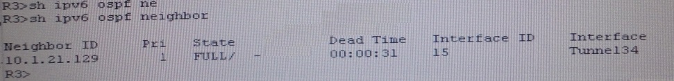
R3 IPV6 OSPF neighbourship is with R4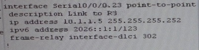
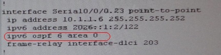
As per above snapshot we cannot see IPV6 neighbourship between R2 & R3 when checked
interface configuration ipv6 ospf area 0 is missing on R2 which is connected to R3
Change required: On R2, IPV6 OSPF routing, Configuration is required to add ipv6 ospf 6 area
0 under interface serial 0/0/0.23
—————————————————–
###EndTicket11###
The implementations group has been using the test bed to do a ‘proof-of-concept’. After
several changes to the network addressing, routing schemes, a trouble ticket has been
opened indicating that the loopback address on R1 (2026::111:1) is not able to ping the
loopback address on DSW2(2026::102:1).
Use the supported commands to isolated the cause of this fault and answer the following
questions.
On which device is the fault condition located?