

what will be the resulting priority value of the VLAN 1015 HSRP group on router DSW2?

If GigabitEthernet1/0/1 on DSW2 is shut down, what will be the resulting priority value of the VLAN 1015 HSRP
group on router DSW2?
Which port state is interface Fa0/2 of switch SW-B in for VLAN1 and 175?

Which port state is interface Fa0/2 of switch SW-B in for VLAN1 and 175?
Which Spanning Tree Protocol has been implemented on switch SW-B?

Which Spanning Tree Protocol has been implemented on switch SW-B?
Which bridge ID belongs to switch SW-A?

Which bridge ID belongs to switch SW-A?
Which port role has interface Fa0/2 of switch SW-A adopted for VLAN 44?

Which port role has interface Fa0/2 of switch SW-A adopted for VLAN 44?
You need to configure SwitchC so that Hosts H1 and H2 can successful ping the server S1
MLS and EIGRP Sim 2
You have been tasked with configuring multilayer SwitchC, which has a partial configuration and has been
attached to RouterC as shown in the topology diagram.
You need to configure SwitchC so that Hosts H1 and H2 can successful ping the server S1. Also SwitchC
needs to be able to ping server S1.
Due to administrative restrictions and requirementsyou should not add/delete vlans, changes VLAN port
assignments or create trunk links
Company policies forbid the use of static or default routing All routes must be learned via EIGRP 65010 routing
protocol.
You do not have access to RouteC, RouterC is correctly configured. No trunking has been configured on
RouterC.
Routed interfaces should use the lowest host on a subnet when possible. The following subnets are available to
implement this solution:
· 172.16.1.0/24
· 192.168.3.32/27
· 192.168.3.64/27
Hosts H1 and H2 are configured with the correct IP address and default gateway.
SwitchC uses Cisco as the enable password.
Routing must only be enabled for the specific subnets shown in the diagram.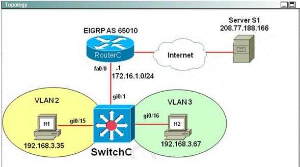
Host1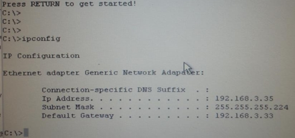
Host 2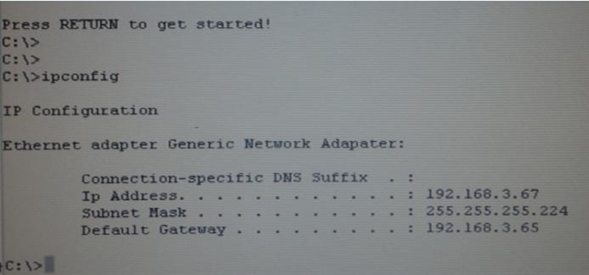
Configure the Multilayer Switch so that PCs from VLAN 2 and VLAN 3 can communicate with the Server.
MLS and EIGRP Sim 1
Configure the Multilayer Switch so that PCs from VLAN 2 and VLAN 3 can communicate with the Server.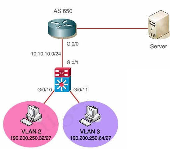
You have been tasked with isolating the cause the these issuer and implementing the appropriate solutions.
VTP Lab Sim 2
Acme is small export company that has an existing enterprise network comprised of 5 switches; CORE,DSW1,
DSW2,ASW1 and ASW2. The topology diagram indicates their desired pre-VLAN spanning tree mapping.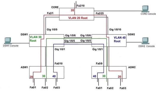
Previous configuration attempts have resulted in the following issues:
– CORE should be the root bridge for VLAN 20; however, DSW1 is currently the root bridge for VLAN 20.
– Traffic for VLAN 30 should be forwarding over thegig 1/0/6 trunk port between DSW1 and DSW2. However
VLAN 30 is currently using gig 1/0/5.
– Traffic for VLAN 40 should be forwarding over thegig 1/0/5 trunk port between DSW1 and DSW2. However
VLAN 40 is currently using gig 1/0/6.
You have been tasked with isolating the cause the these issuer and implementing the appropriate solutions.
You task is complicated by the fact that you only have full access to DSW1, with isolating the cause of these
issues and implementing the appropriate solutions, Your task is complicated by the fact that you only have full
access to DSW1, with the enable secret password cisco. Only limited show command access is provided on
CORE, and DSW2 using the enable 2 level with a password of acme. No configuration changes will be possible
on these routers. No access is provided to ASW1 or ASW2.
To configure the switch click on the host icon that is connected to the switch beway of a serial console cable
VTP Lab Sim 1
The headquarter offices for a book retailer are enhancing their wiring closets with Layer3 switches. The new
distribution-layer switch has been installed and a new access-layer switch cabled to it. Your task is to configure
VTP to share VLAN information from the distribution-layer switch to the access-layer devices. Then, itis
necessary to configure interVLAN routing on the distribution layer switch to route traffic between thedifferent
VLANs that are configured on the access-layer switches; however, it is not necessary for you to make the
specific VLAN port assignments on the access-layer switches. Also, because VLAN database mode is being
deprecated by Cisco, all VLAN and VTP configurations are to be completed in the global configuration mode.
Please reference the following table for the VTP and VLAN information to be configured:

These are your specific tasks:
1. Configure the VTP information with the distribution layer switch as the VTP server
2. Configure the VTP information with the access layer switch as a VTP client
3. Configure VLANs on the distribution layer switch
4. Configure inter-VLAN routing on the distributionlayer switch
5. Specific VLAN port assignments will be made as users are added to the access layer switches in the future.
6. All VLANs and VTP configurations are to completed in the global configuration. To configure the switch click
on the host icon that is connected to the switch beway of a serial console cable.
You are required to accomplishthe following tasks…
STP Lab Sim
The information of the question
You will configure FastEthernet ports 0/12 through 0/24 for users who belong to VLAN 20. Also, all VLAN and
VTP configurations are to be completed in global configuration mode as VLAN database mode is being
deprecated by Cisco. You are required to accomplishthe following tasks:
1. Ensure the switch does not participate in VTP but forwards VTP advertisements received on trunk ports.
2. Ensure all non-trunking interfaces (Fa0/1 to Fa0/24) transition immediately to the forwarding stateof
Spanning-Tree.
3. Ensure all FastEthernet interfaces are in a permanent non-trunking mode.
4. Place FastEthernet interfaces 0/12 through 0/24 in VLAN 20