

Place FastEthernet interfaces 0/12 through 0/24 in VLAN 20
CORRECT TEXT
Refer to the Exhibit.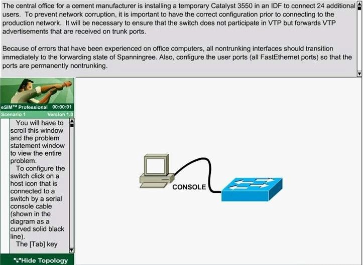
The information of the question
You will configure FastEthernet ports 0/12 through 0/24 for users who belong to VLAN 20. Also, all
VLAN and VTP configurations are to be completed in global configuration mode as VLAN
database mode is being deprecated by Cisco. You are required to accomplish the following tasks:
1. Ensure the switch does not participate in VTP but forwards VTP advertisements received on
trunk ports.
2. Ensure all non-trunking interfaces (Fa0/1 to Fa0/24) transition immediately to the forwarding
state of Spanning-Tree.
3. Ensure all FastEthernet interfaces are in a permanent non-trunking mode.
4. Place FastEthernet interfaces 0/12 through 0/24 in VLAN 20
Drag the questions that you would ask the network administrator before you start the planning from the left to
DRAG DROP
You have been tasked with planning a VLAN solution that will connect a server in one building to several host in another building. The solution should be built using the local VLAN model and Layer 3 switching at the distribution layer. Drag the questions that you would ask the network administrator before you start the planning from the left to the right. Not all questions will be used.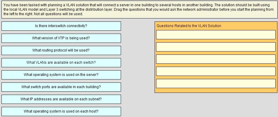
Drag the choices on the left to the boxes on the right that should be included when creating a VLAN-based impl
DRAG DROP
Drag the choices on the left to the boxes on the right that should be included when creating a VLAN-based implementation plan. Not all choices will be used.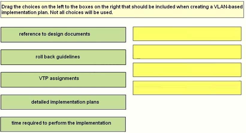
Put the highest level at the top and the lowest level at the bottom
DRAG DROP
Syslog information can generate message up to and including the configured severity level. Organize the levels by dragging each name from the left to the right. Put the highest level at the top and the lowest level at the bottom.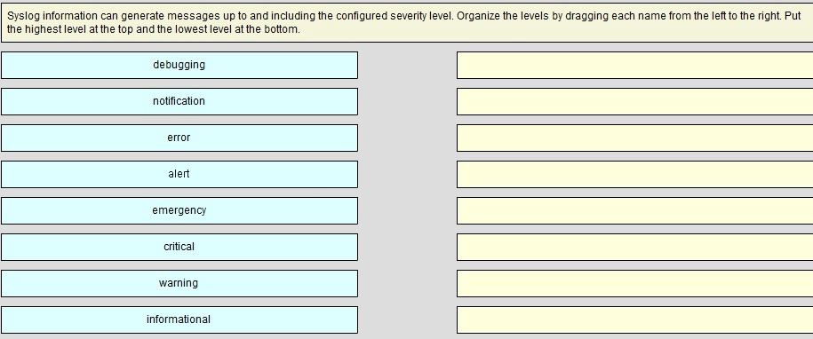
You must accomplish the following tasks?
CORRECT TEXT
Refer to the exhibit.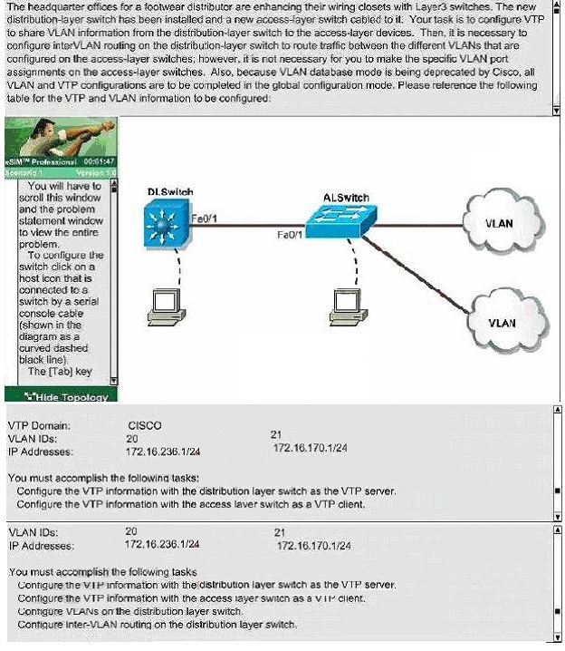
You must accomplish the following tasks?
– Configure the VTP information with the distribution layer switch as the VTP server.
– Configure the VTP information with the access layer switch as a VTP client.
– Configure VLANs on the distribution layer switch.
– Configure inter-VLAN routing on the distribution layer switch.
9b00 Hello Time 2 sec Max Age 20 sec Forward Delay I5 sec Aging Time 300 DSW1#
CORRECT TEXT
Acme is small export company that has an existing enterprise network comprised of 5 switches;
CORE,DSW1,
DSW2,ASW1 and ASW2. The topology diagram indicates their desired pre-VLAN spanning tree
mapping.
Previous configuration attempts have resulted in the following issues:
– CORE should be the root bridge for VLAN 20; however, DSW1 is currently the root bridge for
VLAN 20.
– Traffic for VLAN 30 should be forwarding over the gig 1/0/6 trunk port between DSW1 and
DSW2.
However VLAN 30 is currently using gig 1/0/5.
– Traffic for VLAN 40 should be forwarding over the gig 1/0/5 trunk port between DSW1 and
DSW2.
However VLAN 40 is currently using gig 1/0/6.
You have been tasked with isolating the cause the these issuer and implementing the appropriate
solutions. You task is complicated by the fact that you only have full access to DSW1, with
isolating the cause of these issues and implementing the appropriate solutions, Your task is
complicated by the fact that you only have full access to DSW1, with the enable secret password
cisco. Only limited show command access is provided on CORE, and DSW2 using the enable 2
level with a password of acme. No configuration changes will be possible on these routers. No
access is provided to ASW1 or ASW2.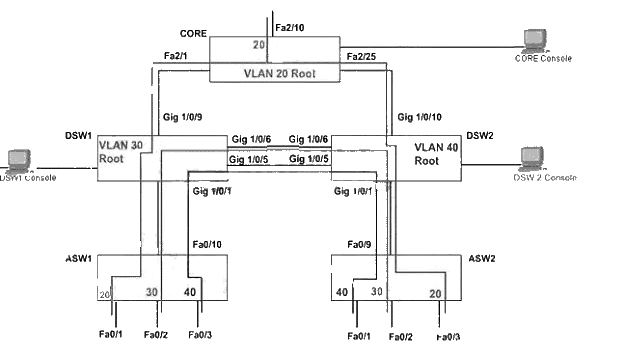
hostname DSW1
!
enable secret 5 $1$wN16$j5RnayatKfxaKxhX30TVo0
!
no aaa new-model
switch 1 provision ws-c3750g-24t
ip subnet-zero
!
no file verify auto
!
spanning-tree mode pvst
spanning-tree extend systen-id
spanning-tree “vlan 20 priority 28672
spanning-tree vlan 30 priority 24576
!
vlan internal allocation policy ascending
!
interface GigabitEthernet1/0/1
description trunk line to ASW1
switchport trunk encapsulation dotlq
switchport mode trunk
switchport nonegotiate
speed 100
duplex full
!
interface GigabitEthernet1/0/2
shutdown
!
interface GigabitEthernet1/0/3
shutdown
!
interface GigabitEthernet1/0/4
shutdown
!
interface GigabitEthernet1/0/5
description trunk line to DSW 2
switchport trunk encapsulation dotlq
switcbport mode trunk
switchport nonegotiate
speed 100
duplex full
!
interface GigabitEthernet1/0/6
description trunk line to DSW 2
switchport trunk encapsulation dotlq
switchport mode trunk
switchport nonegotiate
speed 100
duplex full
!
interface GigabitEthemet1/0/7
shutdown
!
interface GigabitEthemet1/0/8
shutdown
!
Interface GigabitEthernetl/0/9
description trunk line to CORE
switchport trunk encapsulation dotlq
switchport mode trunk
!
end
DSW1# Show sp
DSW1# Show spanning-tree
VLAN0001
Spanning tree enabled protocol ieee
Root ID Priority 32769
Address 0016. 4658. f300
Cost 19
Port 9 (GigabitEthernet/0/9)
Hello Time 2 sec Max Age 20 sec Forward Delay 15 sec
Bridge ID Priority 32769 (priority 32768 sys-id-ext 1)
Address 0016. 46fa. 9b00
Hello Time 2 sec Max Age 20 sec Forward Delay I5 sec
Aging Time 300
VLAN0020
Spanning three enabled protocol ieee
Root ID Priority 28692
Address 0016. 46fa. 9b00
This bridge is the root
Bridge ID Priority 28692 (priority 28672 sys-id-ext 20)
Address 0016. 46fa. 9b00
Hello Time 2 sec Max Age 20 sec Forward Delay I5 sec
Aging Time 300
VLAN0020
Spanning three enabled protocol ieee
Root ID Priority 28692
Address 0016. 46fa. 9b00
This bridge is the root
Bridge ID Priority 28692 (priority 28672 sys-id-ext 20)
Address 0016. 46fa. 9b00
Hello Time 2 sec Max Age 20 sec Forward Delay I5 sec
Aging Time 300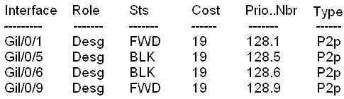
VLAN0030
Spanning three enabled protocol ieee
Root ID Priority 24606
This bridge is the root
Bridge ID Priority 28692 (priority 28672 sys-id-ext 20)
Address 0016. 46fa. 9b00
Hello Time 2 sec Max Age 20 sec Forward Delay I5 sec
Aging Time 300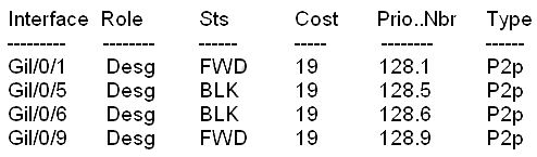
VLAN0040
Spanning three enabled protocol ieee
Root ID Priority 24616
Address 0016. 46fa. 6a00
Cost 19
Port 9 (GigabitEthernet/0/9)
Hello Time 2 sec Max Age 20 sec Forward Delay I5 sec
Bridge ID Priority 32808 (priority 32768 sys-id-ext 40)
Address 0016. 46fa. 9b00
Hello Time 2 sec Max Age 20 sec Forward Delay I5 sec
Aging Time 300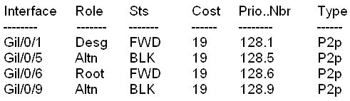
DSW1#
Make switch B the root
CORRECT TEXT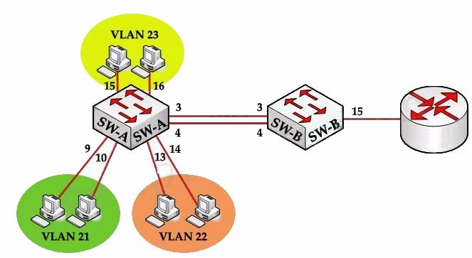
Each of these vlans has one host each on its ports
SVI on vlan 1 – ip 192.168.1.11
Switch B Ports 3, 4 connected to ports 3 and 4 on Switch A
Port 15 connected to Port on Router.
Tasks to do:
1. Use non proprietary mode of aggregation with Switch B being the initiator
— Use LACP with B being in Active mode
2. Use non proprietary trunking and no negotiation
— Use switchport mode trunk and switchport trunk encapsulation dot1q
3. Restrict only to the VLANs needed
— Use either VTP pruning or allowed VLAN list. The preferred method is using allowed VLAN list
4. SVI on VLAN 1 with some ip and subnet given
5. Configure switch A so that nodes other side of Router C are accessible
— on switch A the default gateway has to be configured.
6. Make switch B the root
• SwitchB VTP mode needs to be the same as Switch
CORRECT TEXT
Scenario:
You work for SWITCH.com. They have just added a new switch (SwitchB) to the existing network
as shown in the topology diagram.
RouterA is currently configured correctly and is providing the routing function for devices on
SwitchA and SwitchB. SwitchA is currently configured correctly, but will need to be modified to
support the addition of SwitchB. SwitchB has a minimal configuration. You have been tasked with
competing the needed configuring of SwitchA and SwitchB. SwitchA and SwitchB use Cisco as the
enable password.
Configuration Requirements for SwitchA
The VTP and STP configuration modes on SwitchA should not be modified.
• SwitchA needs to be the root switch for vlans 11, 12, 13, 21, 22 and 23. All other vlans should
be left are their default values.
Configuration Requirements for SwitchB
• Vlan 21
o Name: Marketing
o will support two servers attached to fa0/9 and fa0/10
• Vlan 22
o Name: Sales
o will support two servers attached to fa0/13 and fa0/14
• Vlan 23
o Name: Engineering
o will support two servers attached to fa0/15 and fa0/16
• Access ports that connect to server should transition immediately to forwarding state upon
detecting the connection of a device.
• SwitchB VTP mode needs to be the same as SwitchA.
• SwitchB must operate in the same spanning tree mode as SwitchA
• No routing is to be configured on SwitchB
• Only the SVI vlan 1 is to be configured and it is to use address 192.168.1.11/24
Inter-switch Connectivity Configuration Requirements
• For operational and security reasons trunking should be unconditional and Vlans 1, 21, 22 and
23 should tagged when traversing the trunk link.
• The two trunks between SwitchA and SwitchB need to be configured in a mode that allows for
the maximum use of their bandwidth for all vlans. This mode should be done with a nonproprietary protocol, with SwitchA controlling activation.
• Propagation of unnecessary broadcasts should be limited using manual pruning on this trunk link.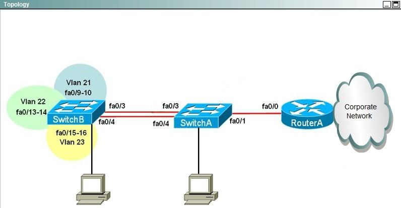
You need to configure SwitchC so that Hosts H1 arid H2 can successful ping the server S1
CORRECT TEXT
You have been tasked with configuring multilayer SwitchC, which has a partial configuration and
has been attached to RouterC as shown in the topology diagram.
You need to configure SwitchC so that Hosts H1 arid H2 can successful ping the server S1. Also
SwitchC needs to be able to ping server SI.
Due to administrative restrictions and requirements you should not add/delete vlans or create
trunk links Company policies forbid the use of static or default routing All routes must be learned
via EIGRP 65010 routing protocol.
You do not have access to RouteC, RouterC is correctly configured. No trunking has been
configured on RouterC.
Routed interfaces should use the lowest host on a subnet when possible. The following subnets
are available to implement this solution:
• 172.16.1.0/24
• 192.168.3.32/27
• 192.168.3.64/27
Hosts H1 and H2 are configured with the correct IP address and default gateway.
SwitchC uses Cisco as the enable password.
Routing must only be enabled for the specific subnets shown in the diagram.
Note: Due to administrative restrictions and requirements you should not add or delete VLANs,
changes VLAN port assignments or create trunks. Company policies forbid the use of static or
default routing. All routes must be learning via the EIGRP routing protocol.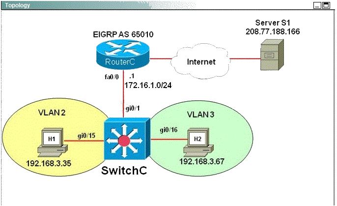
HOST 1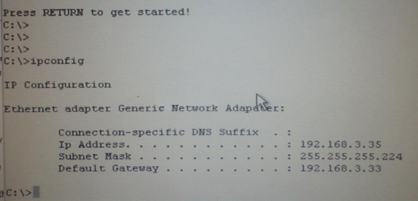
HOST 2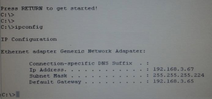
which is the recommended method of providing interVLAN routing?
Refer to the exhibit.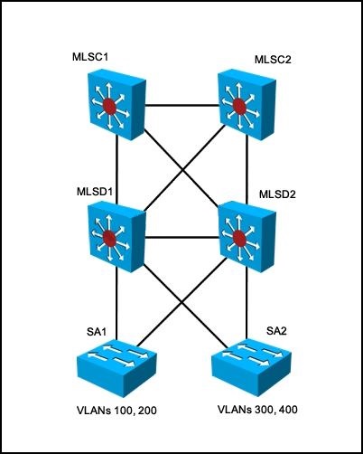
For the configuration shown, which is the recommended method of providing interVLAN routing?