

You task is complicated by the fact that you only have full access to DSW1, with isolating the cause of these
SIMULATION
Acme is small export company that has an existing enterprise network comprised of 5
switches; CORE,DSW1,
DSW2,ASW1 and ASW2. The topology diagram indicates their desired pre-VLAN spanning
tree mapping.
Previous configuration attempts have resulted in the following issues:
– CORE should be the root bridge for VLAN 20; however, DSW1 is currently the root bridge
for VLAN 20.
– Traffic for VLAN 30 should be forwarding over the gig 1/0/6 trunk port between DSW1 and
DSW2.
However VLAN 30 is currently using gig 1/0/5.
– Traffic for VLAN 40 should be forwarding over the gig 1/0/5 trunk port between DSW1 and
DSW2.
However VLAN 40 is currently using gig 1/0/6.
You have been tasked with isolating the cause the these issuer and implementing the
appropriate solutions. You task is complicated by the fact that you only have full access to
DSW1, with isolating the cause of these issues and implementing the appropriate solutions,
Your task is complicated by the fact that you only have full access to DSW1, with the enable
secret password cisco. Only limited show command access is provided on CORE, and
DSW2 using the enable 2 level with a password of acme. No configuration changes will be
possible on these routers. No access is provided to ASW1 or ASW2.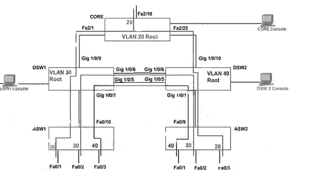
hostname DSW1
!
enable secret 5 $1$wN16$j5RnayatKfxaKxhX30TVo0
!
no aaa new-model
switch 1 provision ws-c3750g-24t
ip subnet-zero
!
no file verify auto
!
spanning-tree mode pvst
spanning-tree extend systen-id
spanning-tree “vlan 20 priority 28672
spanning-tree vlan 30 priority 24576
!
vlan internal allocation policy ascending
!
interface GigabitEthernet1/0/1
description trunk line to ASW1
switchport trunk encapsulation dotlq
switchport mode trunk
switchport nonegotiate
speed 100
duplex full
!
interface GigabitEthernet1/0/2
shutdown
!
interface GigabitEthernet1/0/3
shutdown
!
interface GigabitEthernet1/0/4
shutdown
!
interface GigabitEthernet1/0/5
description trunk line to DSW 2
switchport trunk encapsulation dotlq
switcbport mode trunk
switchport nonegotiate
speed 100
duplex full
!
interface GigabitEthernet1/0/6
description trunk line to DSW 2
switchport trunk encapsulation dotlq
switchport mode trunk
switchport nonegotiate
speed 100
duplex full
!
interface GigabitEthemet1/0/7
shutdown
!
interface GigabitEthemet1/0/8
shutdown
!
Interface GigabitEthernetl/0/9
description trunk line to CORE
switchport trunk encapsulation dotlq
switchport mode trunk
!
end
DSW1# Show sp
DSW1# Show spanning-tree
VLAN0001
Spanning tree enabled protocol ieee
Root ID Priority 32769
Address 0016. 4658. f300
Cost 19
Port 9 (GigabitEthernet/0/9)
Hello Time 2 sec Max Age 20 sec Forward Delay 15 sec
Bridge ID Priority 32769 (priority 32768 sys-id-ext 1)
Address 0016. 46fa. 9b00
Hello Time 2 sec Max Age 20 sec Forward Delay I5 sec
Aging Time 300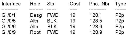
VLAN0020
Spanning three enabled protocol ieee
Root ID Priority 28692
Address 0016. 46fa. 9b00
This bridge is the root
Bridge ID Priority 28692 (priority 28672 sys-id-ext 20)
Address 0016. 46fa. 9b00
Hello Time 2 sec Max Age 20 sec Forward Delay I5 sec
Aging Time 300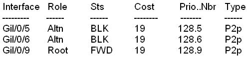
VLAN0020
Spanning three enabled protocol ieee
Root ID Priority 28692
Address 0016. 46fa. 9b00
This bridge is the root
Bridge ID Priority 28692 (priority 28672 sys-id-ext 20)
Address 0016. 46fa. 9b00
Hello Time 2 sec Max Age 20 sec Forward Delay I5 sec
Aging Time 300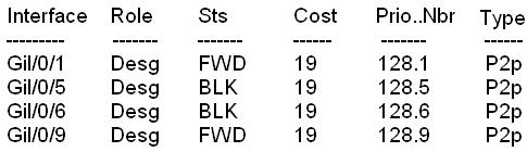
VLAN0030
Spanning three enabled protocol ieee
Root ID Priority 24606
This bridge is the root
Bridge ID Priority 28692 (priority 28672 sys-id-ext 20)
Address 0016. 46fa. 9b00
Hello Time 2 sec Max Age 20 sec Forward Delay I5 sec
Aging Time 300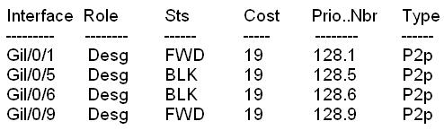
VLAN0040
Spanning three enabled protocol ieee
Root ID Priority 24616
Address 0016. 46fa. 6a00
Cost 19
Port 9 (GigabitEthernet/0/9)
Hello Time 2 sec Max Age 20 sec Forward Delay I5 sec
Bridge ID Priority 32808 (priority 32768 sys-id-ext 40)
Address 0016. 46fa. 9b00
Hello Time 2 sec Max Age 20 sec Forward Delay I5 sec
Aging Time 300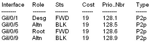
DSW1#
You have been tasked with implementing the above access control as a pre-condition to installing the servers.
SIMULATION
AAAdot1x Lab
Acme is a small shipping company that has an existing enterprise network comprised of 2
switches;DSW1 and
ASW2. The topology diagram indicates their layer 2 mapping. VLAN 40 is a new VLAN that
will be used to provide the shipping personnel access to the server. For security reasons, it
is necessary to restrict access to
VLAN 20 in the following manner:
– Users connecting to ASW1’s port must be authenticate before they are given access to the network.
-Authentication is to be done via a Radius server:
– Radius server host: 172.120.39.46
– Radius key: rad123
– Authentication should be implemented as close to the host device possible.
– Devices on VLAN 20 are restricted to in the address range of 172.120.40.0/24.
– Packets from devices in the address range of 172.120.40.0/24 should be passed on VLAN 20.
– Packets from devices in any other address range should be dropped on VLAN 20.
– Filtering should be implemented as close to the server farm as possible.
The Radius server and application servers will be installed at a future date. You have been
tasked with implementing the above access control as a pre-condition to installing the
servers. You must use the available
IOS switch features.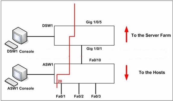
Which VTP information does a Catalyst switch advertise on its trunk ports when using VTP?
Two Company switches are connected via a trunk using VTP. Which VTP information does a
Catalyst switch advertise on its trunk ports when using VTP? (Select two)
Which two of the following statements are true?
Refer to the exhibit.
Which two of the following statements are true? (Choose two)
which two prevents VTP information from propagating between switches?
You need to investigate a VTP problem between two Company switches. The lack of which
two prevents VTP information from propagating between switches? (Select two)
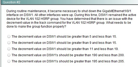
What need to be done to make the group for VLAN 101 function properly?


What need to be done to make the group for VLAN 101 function properly?
What is the default VTP advertisement intervals in Catalyst switches that are in server or client mode?
R1 and R2 are switches that communicate via VTP. What is the default VTP advertisement
intervals in Catalyst switches that are in server or client mode?
What needs to be done to make the group function properly?
HOTSPOT
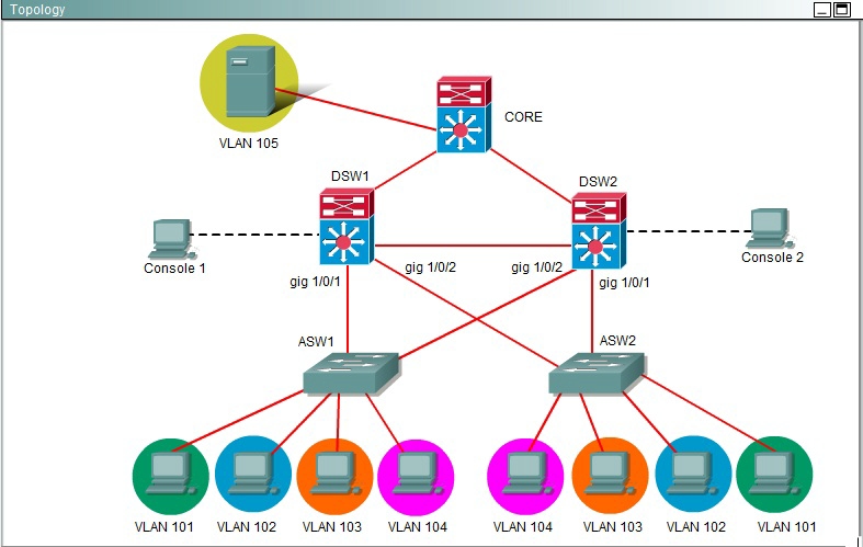
What needs to be done to make the group function properly?
Where will the broadcast propagate?
Refer to the exhibit.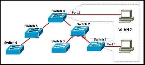
VTP has been enabled on the trunk links between all switches within the
TEST domain. An administrator has recently enabled VTP pruning. Port 1 on Switch 1 and
port 2 on Switch 4 are assigned to VLAN 2. A broadcast is sent from the host connected to Switch 1.
Where will the broadcast propagate?
what will be the resulting priority value of the VLAN 105 HSRP group on router DSW2?
HOTSPOT


If GigabitEthemet1/0/1 on DSW2 is shutdown, what will be the resulting priority value of the VLAN 105 HSRP group on router DSW2?