

CORRECT TEXT
This topology contains 3 routers and 1 switch. Complete the topology.
Drag the appropriate device icons to the labeled Device
Drag the appropriate connections to the locations labeled Connections.
Drag the appropriate IP addresses to the locations labeled IP address
(Hint: use the given host addresses and Main router information)
To remove a device or connection, drag it away from the topology.
Use information gathered from the Main router to complete the configuration of any additional
routers.
No passwords are required to access the Main router. The config terminal command has been
disabled for the HQ router. The router does not require any configuration.
Configure each additional router with the following: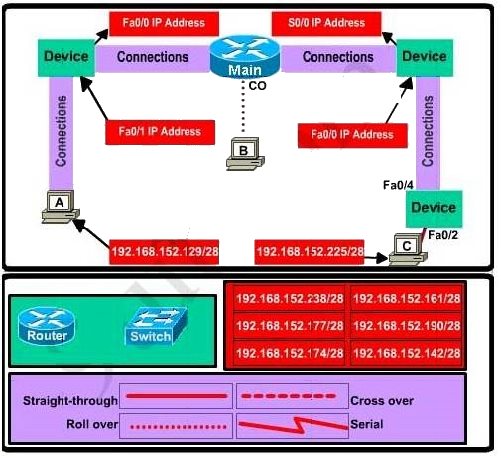
Configure the interfaces with the correct IP address and enable the interfaces.
Set the password to allow console access to consolepw
Set the password to allow telnet access to telnetpw
Set the password to allow privilege mode access to privpw
Note: Because routes are not being added to the configurations, you will not be able to ping
through the internetwork.
All devices have cable autosensing capabilities disabled.
All hosts are PC’s

Answer: ….
Explanation:
Specify appropriate devices and drag them on the “Device” boxes
For the device at the bottom-right box, we notice that it has 2 interfaces Fa0/2 and Fa0/4;
moreover the link connects the PC on the right with the device on the bottom-right is a straightthrough link -> it is a switch
The question stated that this topology contains 3 routers and 1 switch -> two other devices are
routers
Place them on appropriate locations as following:
(Host D and host E will be automatically added after placing two routers. Click on them to access
neighboring routers)
Specify appropriate connections between these devices:
+ The router on the left is connected with the Main router through FastEthernet interfaces: use a
crossover cable
+ The router on the right is connected with the Main router through Serial interfaces: use a serial
cable
+ The router on the right and the Switch: use a straight-through cable
+ The router on the left and the computer: use a crossover cable
(To remember which type of cable you should use, follow these tips:
– To connect two serial interfacesof 2 routers we use serial cable
– To specify when we use crossover cable or straight-through cable, we should remember:
Group 1:Router, Host, Server
Group 2:Hub, Switch
One device in group 1 + One device in group 2: use straight-through cable
Two devices in the same group: use crossover cable
For example: we use straight-through cable to connect switch to router, switch to host, hub to host,
hub to server… and we use crossover cable to connect switch to switch, switch to hub, router to
router, host to host… )
Assign appropriate IP addresses for interfaces:
From Main router, use show running-config command:
(Notice that you may see different IP addresses in the real CCNA exam, the ones shown above
are just used for demonstration)
From the output we learned that the ip address of Fa0/0 interface of the Main router is
192.168.152.177/28. This address belongs to a subnetwork which has:
Increment: 16 (/28 = 255.255.255.240 or 1111 1111.1111 1111.1111 1111.11110000)
Network address: 192.168.152.176 (because 176 = 16 * 11 and 176 < 177)Broadcast address: 192.168.152.191 (because 191 = 176 + 16 – 1)
And we can pick up an ip address from the list that belongs to this subnetwork: 192.168.152.190
and assign it to the Fa0/0 interface the router on the left
Use the same method for interface Serial0/0 with an ip address of 192.168.152.161
Increment: 16
Network address: 192.168.152.160 (because 160 = 16 * 10 and 160 < 161)
Broadcast address: 192.168.152.175 (because 176 = 160 + 16 – 1)
-> and we choose 192.168.152.174for Serial0/0 interface of the router on the right
Interface Fa0/1 of the router on the left
IP (of the computer on the left) : 192.168.152.129/28
Increment: 16
Network address: 192.168.152.128 (because 128 = 16 * 8 and 128 < 129)
Broadcast address: 192.168.152.143 (because 143 = 128 + 16 – 1)
-> we choose 192.168.152.142from the list
Interface Fa0/0 of the router on the right
IP (of the computer on the left) : 192.168.152.225/28
Increment: 16
Network address: 192.168.152.224 (because 224 = 16 * 14 and 224 < 225)
Broadcast address: 192.168.152.239 (because 239 = 224 + 16 – 1)
-> we choose 192.168.152.238from the list
Let’s have a look at the picture below to summarize
Configure two routers on the left and right with these commands:
Router1 = router on the left
Assign appropriate IP addresses to Fa0/0 & Fa0/1 interfaces:
Router1>enable
Router1#configure terminal
Router1(config)#interface fa0/0
Router1(config-if)#ip address 192.168.152.190 255.255.255.240
Router1(config-if)#no shutdown
Router1(config-if)#interface fa0/1
Router1(config-if)#ip address 192.168.152.142 255.255.255.240
Router1(config-if)#no shutdown
Set passwords (configure on two routers)
+ Console password:
Router1(config-if)#exit
Router1(config)#line console 0
Router1(config-line)#password consolepw
Router1(config-line)#login
Router1(config-line)#exit
+ Telnet password:
Router1(config)#line vty 0 4Router1(config-line)#password telnetpw
Router1(config-line)#login
Router1(config-line)#exit
+ Privilege mode password:
Router1(config)#enable password privpw
Save the configuration:
Router1(config)#exit
Router1#copy running-config startup-config
Configure IP addresses of Router2 (router on the right)
Router2>enable
Router2#configure terminal
Router2(config)#interface fa0/0
Router2(config-if)#ip address 192.168.152.238 255.255.255.240
Router2(config-if)#no shutdown
Router2(config-if)#interface serial0/0
Router2(config-if)#ip address 192.168.152.174 255.255.255.240
Router2(config-if)#no shutdown and set console, telnet and privilege mode passwords for Router2
as we did for Router1, remember to save the configuration when you finished
Always a large fan of linking to bloggers that I like but dont get a great deal of link like from.
0
0