

what is causing this problem?
— Exhibit —
user@R1> show bgp neighbor 172.10.3.201
Peer: 172.10.3.201+54714 AS 64512 Local: 172.10.3.202+179 AS 64513
Type: External State: Established Flags:
Last State: OpenConfirm Last Event: RecvKeepAlive
Last Error: None
Export: [ export ]
Options:
Local Address: 172.10.3.202 Holdtime: 90 Preference: 170 Local AS: 64513
Local System AS: 0
Number of flaps: 0
Peer ID. 10.247.194.254 Local ID. 10.247.24.6 Active Holdtime: 90
Keepalive Interval: 30 Peer index: 0
BFD. disabled, down
Local Interface: ge-0/0/0.500
NLRI for restart configured on peer: inet-unicast
NLRI advertised by peer: inet-unicast
NLRI for this session: inet-unicast
Peer supports Refresh capability (2)
Restart time configured on the peer: 120
Stale routes from peer are kept for: 300
Restart time requested by this peer: 120
NLRI that peer supports restart for: inet-unicast
NLRI that restart is negotiated for: inet-unicast
NLRI of received end-of-rib markers: inet-unicast
NLRI of all end-of-rib markers sent: inet-unicast
Peer supports 4 byte AS extension (peer-as 64512)
Peer does not support Addpath
Table inet.0 Bit: 30000
RIB State: BGP restart is complete
RIB State: VPN restart is complete
Send state: in sync
Active prefixes: 7
Received prefixes: 7
Accepted prefixes: 7
Suppressed due to damping: 0
Advertised prefixes: 30
Last traffic (seconds): Received 5 Sent 18 Checked 8
Input messages: Total 40 Updates 3 Refreshes 0 Octets 877
Output messages: Total 55 Updates 13 Refreshes 0 Octets 1764
Output Queue[2]: 0
— Exhibit —
Refer to the Exhibit.
A customer reports that BGP graceful restart is not working on R1. After a Routing Engine failover,
R1 did not set the restart state bit in its Open message. The customer provides the BGP neighbor
output shown in the exhibit.
Referring the exhibit, what is causing this problem?
Which action will resolve the problem?
— Exhibit –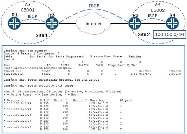
— Exhibit —
Refer to the Exhibit.
You are asked to assist with a problem with a new EBGP peering between Site 1 and Site 2.
Referring to the exhibit, Site 1 is not receiving the 100.100.0.0/16 routes from Site 2.
Which action will resolve the problem?
What should you do on R1 to resolve this problem?
— Exhibit –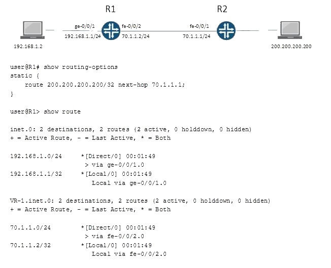
— Exhibit —
Refer to the Exhibit.
On R1, the interface fe-0/0/1 is assigned to the default routing instance and fe-0/0/2 is assigned to
a virtual router instance named VR-1.
Referring to the exhibit, the static route 200.200.200.200/32 is missing from the routing table of the
default routing instance.
What should you do on R1 to resolve this problem?
Which change should the engineer make to accomplish this task?
— Exhibit —
[edit routing-instances]
user@router# show vr1 routing-options
instance-import [ vr1 vr2 ];
[edit routing-instances]
user@router# show vr2 routing-options
instance-import [ vr1 vr2 ];
[edit routing-instances]
user@router# top show policy-options policy-statement vr1
term 1 {
from instance vr1;
then accept;
}
term 2 {
then reject;
}
[edit routing-instances]
user@router# top show policy-options policy-statement vr2
term 1 {
from instance vr2;
then accept;
}
term 2 {
then reject;
}
— Exhibit —
Refer to the Exhibit.
A network engineer wants to leak routes between routing instances vr1 and vr2. No routes from
vr2 are showing up in vr1.
Which change should the engineer make to accomplish this task?
What are two causes for this behavior?
— Exhibit —
protocols {
bgp {
group isps {
type external;
peer-as 13090194;
multipath multiple-as;
neighbor ;
neighbor ;
}
}
}
— Exhibit —
Refer to the Exhibit.
The exhibit shows the complete BGP configuration for a router. The network operator reports that
both peering sessions are up, but the router is not conducting per-flow load balancing over the
connections to these two peers.
What are two causes for this behavior? (Choose two.)
Which statement explains this discrepancy?
— Exhibit —
policy-options {
policy-statement accept-static {
from protocol static;
then accept;
}
}
— Exhibit —
Refer to the Exhibit.
The policy shown in the exhibit is deployed on a router and used as the only BGP export policy.
The router is sending only one BGP route to its peers. However, when you run the CLI command
test policy accept-static 0.0.0.0/0, the policy matches thousands of routes.
Which statement explains this discrepancy?
what is the expected result?
— Exhibit —
policy-statement test_route_filter {
term 1 {
from {
route-filter 192.168.0.0/16 longer;
route-filter 192.168.1.0/24 longer {
metric 5;
accept;
}
route-filter 192.168.0.0/8 orlonger accept;
}
then {
metric 10;
accept;
}
}
term 2 {
then {
metric 20;
accept;
}
}
}
— Exhibit —
Refer to the Exhibit.
Given test route 192.168.1.0/24 and the configuration shown in the exhibit, what is the expected
result?
what else must you do?
— Exhibit –-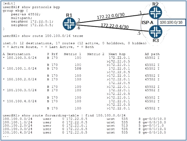
— Exhibit —
Refer to the Exhibit.
Your network has two connections to your ISP. You have been asked to load-balance traffic
across both links that connect to your ISP. You have enabled multipath for this peer, but you are
still not getting the expected load balancing.
Given the information shown in the exhibit, what else must you do?
Which port is attached to the root bridge of MSTI 2?
— Exhibit –(MSTI 2 regional root: 16386.2c:6b:f5:3e:f8:01)
{master:0}
user@switch> show spanning-tree interface
Spanning tree interface parameters for instance 0
Interface Port ID Designated Designated Port State Role
port ID bridge ID Cost
ge-0/0/6.0 128:519 128:519 16384.80711fbc 20000 BLK ALT
ge-0/0/9.0 128:522 128:522 53248.2c6bf591a441 20000 FWD DESG
ge-0/0/10.0 128:523 128:523 8192.80711fbe8110 20000 FWD ROOT
ge-0/0/12.0 128:525 128:525 49152.2c6bf53ef801 20000 BLK ALT
[…]
— Exhibit —
Refer to the Exhibit.
While troubleshooting an MSTP operation in your network, you see the output shown in the exhibit
on one of your switches. You know that the MSTI 2 regional root bridge ID is
16386.2c:6b:f5:3e:f8:01.
Which port is attached to the root bridge of MSTI 2?
What is the cause of this problem?
— Exhibit –-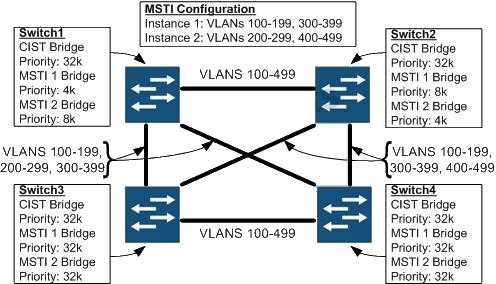
— Exhibit —
Refer to the Exhibit.
The exhibit shows a small switched network, some details about the MSTP configuration in the
network, and the VLANs that are trunked over each link. When Switch2 reboots, users in VLAN
400 on Switch3 report that they lose connectivity to resources in VLAN 400 on Switch4.
What is the cause of this problem?